
Ship pipeline tightness temporary device

A temporary and marine technology, applied in the direction of pipe components, data processing applications, pipes/pipe joints/pipe fittings, etc., it can solve the problems of oil and water quality accidents of large equipment, leakage and dismantling of pipeline tightness temporary devices, and high labor costs. , to achieve the effect of convenient installation and unloading of circular plates, eliminating quality accidents, and saving repeated material costs and labor costs

Inactive Publication Date: 2019-07-26
HUDONG ZHONGHUA SHIPBUILDINGGROUP
View PDF10 Cites 0 Cited by
  • Summary
  • Abstract
  • Description
  • Claims
  • Application Information

AI Technical Summary

Problems solved by technology

[0005] 3) Some systems involve a very large area, and the entire ship is arranged. There is a single system that spans regions and operations areas, and construction spans labor teams and shifts
[0006] 4) Due to the different personnel in the construction work area, construction labor team, and construction team, there are often leaks in the process of segmental tightness or leakage of pipeline tightness temporary devices after the end of the tightness, especially in the work area, labor team 1. The so-called "blind bed" forgetting to disassemble often occurs at the demarcation point of the construction area of ​​the team. Once the equipment is moved, it will either damage the equipment or overload the trip, which will seriously cause large-scale equipment to cut off oil and water, resulting in considerable quality accidents.
[0007] 5) Temporary devices for pipeline tightness are cut and manufactured by each team or construction personnel in each production operation area with thin iron sheets according to their own needs. They have different shapes, sizes, and thicknesses. They cannot be used universally, and there is no special person after use. Will take it in, make one and make one, there is a lot of waste, and the cost of manual production is also very high

Method used


Image

  • Ship pipeline tightness temporary device
  • Ship pipeline tightness temporary device
  • Ship pipeline tightness temporary device

Examples


Embodiment Construction

[0028] The following will clearly and completely describe the technical solutions in the embodiments of the present invention with reference to the accompanying drawings in the embodiments of the present invention. Obviously, the described embodiments are only some, not all, embodiments of the present invention. Based on the embodiments of the present invention, all other embodiments obtained by persons of ordinary skill in the art without making creative efforts belong to the protection scope of the present invention.

[0029] In describing the present invention, it should be understood that the terms "longitudinal", "transverse", "upper", "lower", "front", "rear", "left", "right", "vertical", The orientation or positional relationship indicated by "horizontal", "top", "bottom", "inner", "outer", etc. are based on the orientation or positional relationship shown in the drawings, and are only for the convenience of describing the present invention and simplifying the descriptio...


PUM


Abstract

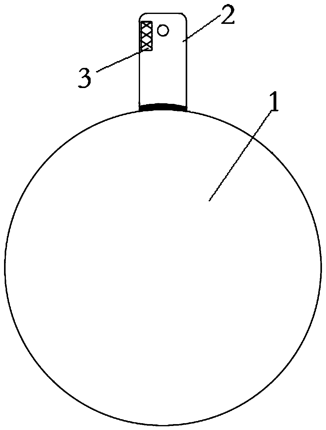
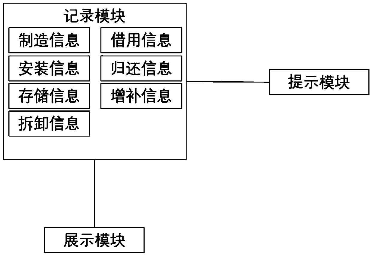
The invention discloses a ship pipeline tightness temporary device. The temporary device comprises a circular plate for blocking a pipeline so that a closed space can be formed, and a handle; one endof the handle is fixed to the circular plate; the handle is provided with marks; and the marks comprise the diameter of pipelines to which the temporary device is applicable, the pressure rating whichthe temporary device can withstand, the thickness of the circular plate, and the serial number of the temporary device. The temporary device has the beneficial effect that by comparing a borrowing information real-name registration form with an installation information real-name registration form of the pipeline tightness temporary device of all ships, production management personnel and production supervisors can easily and accurately know, master and track the pipeline construction status at production sites from the information.

Description

technical field [0001] The invention belongs to the field of shipbuilding, and specifically relates to a ship dock, berth stage or wharf stage. Before the pipeline passes through water, gas, oil and other media, a tightness test must be carried out. Before the tightness test, the pipeline must be at a certain connection point. Install a sealing device to form a closed space. Finally, pressurize the closed space of the pipeline to 1.5 times the working design pressure of the pipeline, and then check whether there is any leakage point at each connection of the entire pipeline system. If there is a leak, the on-site Workers carry out rectification until the pressure can be stabilized within the range required by the process. The device of the present invention is a set of devices that are manufactured for different specifications and pressures of pipelines on board. Background technique [0002] As a blood vessel on board, the pipeline provides oil, gas, water, steam and other ...

Claims


Application Information

Patent Timeline
Patent Type & Authority Applications(China)
IPC IPC(8): F16L55/115G06Q10/08G06Q50/04
CPCF16L55/115G06Q10/087G06Q50/04Y02P90/30
Inventor 张治军
Owner HUDONG ZHONGHUA SHIPBUILDINGGROUP
Learn More