insole puncher
A technology of hole punch and insole, applied in the field of hole punch, can solve the problems of insole crumb injury, human hand injury, etc., and achieve the effect of avoiding tool injury
- Summary
- Abstract
- Description
- Claims
- Application Information
AI Technical Summary
Problems solved by technology
Method used
Image

Examples
Embodiment 1
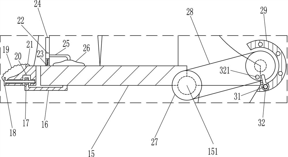
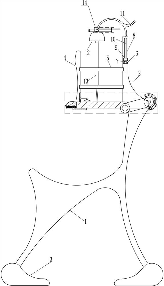
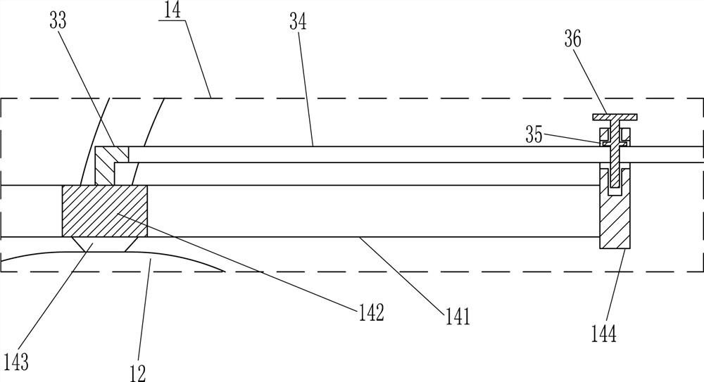
[0016] An insole puncher such as Figure 1-3 As shown, it includes a mounting frame 1, a mounting block 2, a base 3, a mounting plate 4, a connecting rod 5, a bearing seat 6, a first rotating rod 7, a first sliding rail 8, a first sliding block 9, a strut 10, Arc rod 11, servo motor 12, drill pipe 13, moving mechanism 14, rotating plate 15, rotating shaft 151, fixed rod 16, first screw rod 18, connecting rope 19 and bump 21, the bottom of mounting frame 1 is provided with base 3, The mounting frame 1 is connected to the base 3 by means of bolt connection, the top of the mounting frame 1 is provided with a mounting block 2, the mounting frame 1 is connected to the mounting block 2 by a bolt connection, and the middle and lower parts of the mounting block 2 are provided with connecting rods 5, The rear side of the left end of the connecting rod 5 on the upper and lower sides is provided with a mounting plate 4, and the upper part of the front side of the mounting block 2 is prov...
Embodiment 2
[0018] An insole puncher such as Figure 1-3 As shown, it includes a mounting frame 1, a mounting block 2, a base 3, a mounting plate 4, a connecting rod 5, a bearing seat 6, a first rotating rod 7, a first sliding rail 8, a first sliding block 9, a strut 10, Arc rod 11, servo motor 12, drill pipe 13, moving mechanism 14, rotating plate 15, rotating shaft 151, fixed rod 16, first screw rod 18, connecting rope 19 and bump 21, the bottom of mounting frame 1 is provided with base 3, The top of the mounting frame 1 is provided with a mounting block 2, and the middle and lower parts of the mounting block 2 are provided with a connecting rod 5, and the upper and lower sides of the connecting rod 5 are provided with a mounting plate 4 on the left end rear side, and the upper part of the mounting block 2 is provided with a bearing seat 6. The first rotating rod 7 is arranged in the bearing seat 6, and the top of the first rotating rod 7 is connected with the first slide rail 8. The sl...
Embodiment 3
[0021] An insole puncher such as Figure 1-3 As shown, it includes a mounting frame 1, a mounting block 2, a base 3, a mounting plate 4, a connecting rod 5, a bearing seat 6, a first rotating rod 7, a first sliding rail 8, a first sliding block 9, a strut 10, Arc rod 11, servo motor 12, drill pipe 13, moving mechanism 14, rotating plate 15, rotating shaft 151, fixed rod 16, first screw rod 18, connecting rope 19 and bump 21, the bottom of mounting frame 1 is provided with base 3, The top of the mounting frame 1 is provided with a mounting block 2, and the middle and lower parts of the mounting block 2 are provided with a connecting rod 5, and the upper and lower sides of the connecting rod 5 are provided with a mounting plate 4 on the left end rear side, and the upper part of the mounting block 2 is provided with a bearing seat 6. The first rotating rod 7 is arranged in the bearing seat 6, and the top of the first rotating rod 7 is connected with the first slide rail 8. The sl...
PUM
 Abstract
Description
Claims
Application Information
 - R&D
- Intellectual Property
- Life Sciences
- Materials
- Tech Scout
- Unparalleled Data Quality
- Higher Quality Content
- 60% Fewer Hallucinations
Browse by: Latest US Patents, China's latest patents, Technical Efficacy Thesaurus, Application Domain, Technology Topic, Popular Technical Reports.
© 2025 PatSnap. All rights reserved.Legal|Privacy policy|Modern Slavery Act Transparency Statement|Sitemap|About US| Contact US: help@patsnap.com