Automobile electronic hand brake assembling and welding device
An electronic handbrake, welding device technology, applied in welding equipment, non-electric welding equipment, manufacturing tools and other directions, can solve the problems of easy manual fatigue, low positioning accuracy, large manual assembly errors, etc., to improve consistency and pass rate, achieve Assembly and soldering, avoiding the effect of matching errors
- Summary
- Abstract
- Description
- Claims
- Application Information
AI Technical Summary
Problems solved by technology
Method used
Image
Examples
Embodiment 1
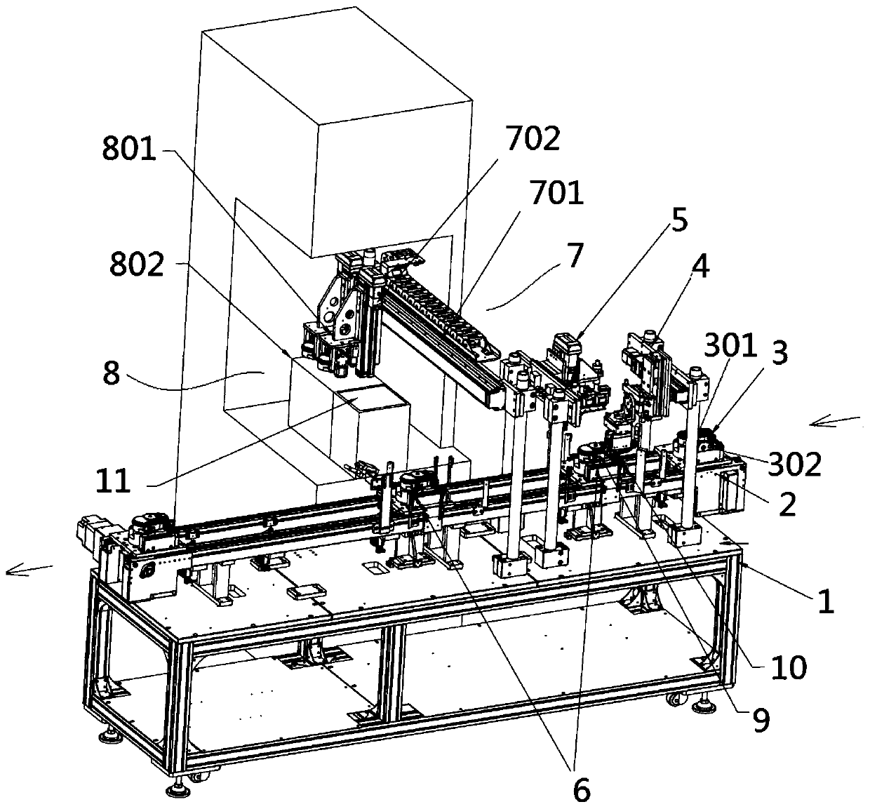
[0080] Such as figure 1 Shown, a kind of automobile electronic handbrake assembly and welding device, it comprises frame 1, and described frame 1 is provided with transmission mechanism 2, and described transmission mechanism 2 is provided with frock jig 3, and described transmission mechanism 2 The upper part is equipped with a clamping and turning mechanism 4, a suction and placement mechanism 5, a positioning detection mechanism 6, a YZ moving component 7 and an ultrasonic welding device 8. The ultrasonic welding device 8 includes a welding supply clamping mechanism 801 and an ultrasonic welding machine 802. The tooling fixture 3 is provided with a body position 301 and a vertical upper cover position 302; the YZ moving assembly 7 includes a Y-axis moving module 701 and a Z-axis moving module 702, and the Z-axis moving module 702 is connected to the Y-axis moving module 702. The axis moving module 701 is slidably connected, and the welding supply clamping mechanism 801 is s...
Embodiment 2
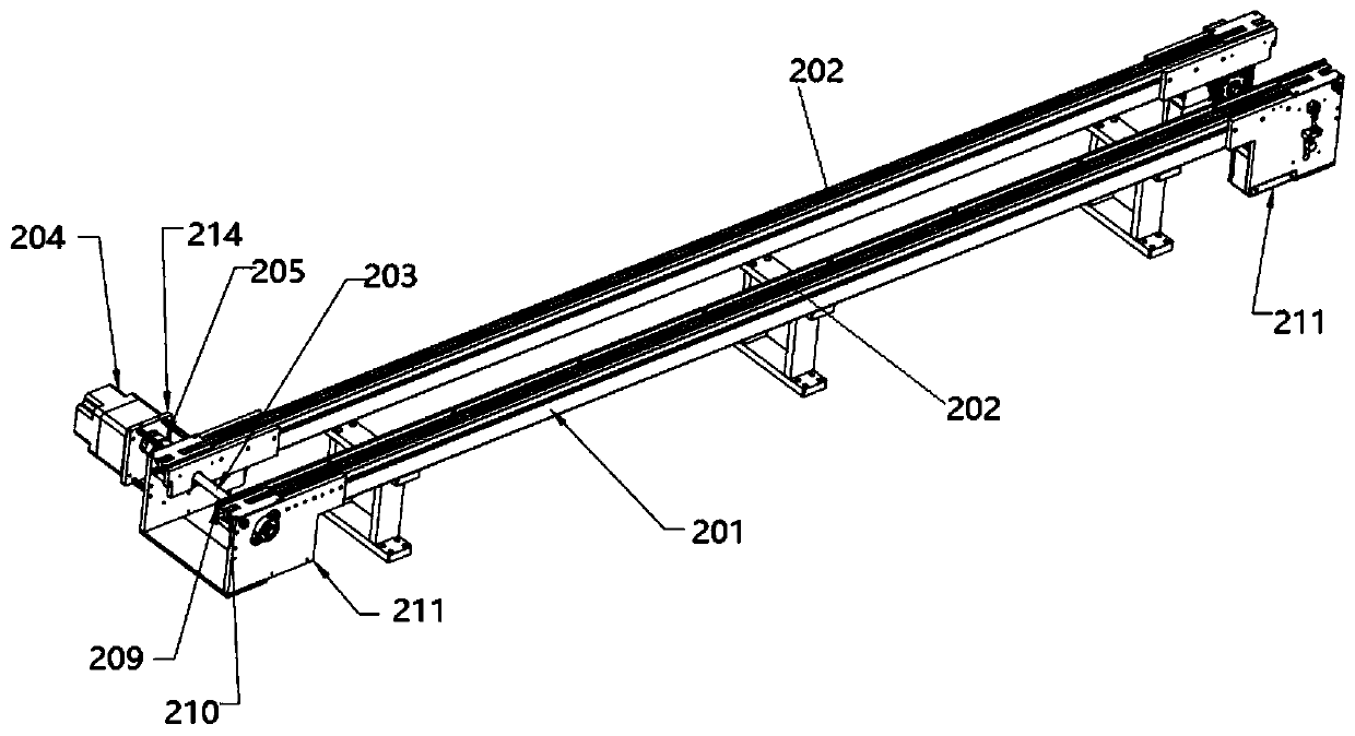
[0086] On the basis of Example 1, such as Figure 2~Figure 5 As shown, the transmission mechanism 2 includes a bracket 201, on which at least two rolling chains 202 are arranged, and one end of the bracket 201 is provided with a driving shaft 203, a driving motor 204, and a coupling 205, and the driving Motor 204 is connected with driving shaft 203 by coupling 205, and described driving shaft 203 is connected with rolling chain 202 by driving sprocket 215; Tension sprocket 207.
[0087] Further, both ends of the bracket 201 are provided with side plates 211 , and the driving motor 204 is fixed on the side plates 211 through the motor bracket 214 .
[0088]Further, the drive shaft 203 is connected with the coupling 205 through a bearing. One side of the driving sprocket 215 is provided with a tensioning block 208 , and the tensioning block 208 is connected with the rolling chain 202 . On the support 201 , one end of the rolling chain 202 is provided with a guide bar 209 and ...
Embodiment 3
[0090] On the basis of Example 2, such as Figure 6~Figure 8 As shown, the tooling fixture 3 includes a tooling base plate 303, a body mold cavity 304 with a body position 301 inside, and a loam cake cavity 305 with a vertical upper cover position 302 inside, and the body mold cavity 304 and the loam mold The cavity 305 is connected with the tooling base plate 303, and the bottom of the tooling base plate 303 is provided with an anti-skid plate 306, a positioning block 307, a guide groove 308 connected with the rolling chain 202, and a positioning guide sleeve 309. The positioning guide sleeve 309 is located in the middle of the tooling bottom plate 303 .
PUM
 Abstract
Description
Claims
Application Information
 - R&D
- Intellectual Property
- Life Sciences
- Materials
- Tech Scout
- Unparalleled Data Quality
- Higher Quality Content
- 60% Fewer Hallucinations
Browse by: Latest US Patents, China's latest patents, Technical Efficacy Thesaurus, Application Domain, Technology Topic, Popular Technical Reports.
© 2025 PatSnap. All rights reserved.Legal|Privacy policy|Modern Slavery Act Transparency Statement|Sitemap|About US| Contact US: help@patsnap.com


