Guide control mechanism for pneumatic lifting table

A technology of pneumatic lifting and guiding control, which is applied to desks, desks, and mechanical equipment that can change the height of the desk. , the effect of high guiding accuracy

Pending Publication Date: 2019-07-26
张春勤
View PDF0 Cites 3 Cited by
  • Summary
  • Abstract
  • Description
  • Claims
  • Application Information

AI Technical Summary

Problems solved by technology

[0003] Pneumatic lifting tables on the market now generally use the inner and outer sleeves and the plane needle roller bearings matched with the inner sleeves to realize the guiding function. Because the inner and outer sleeves are extruded or rolled from aluminum or steel, the guide plane The accuracy is poor, the gap between the sleeve and the needle roller is large, the table is easy to shake, and the size of the needle roller needs to be assembled in stages, which is very inconvenient and the quality is not stable
The dynamic load capacity of the pneumatic lift tables on the market is relatively small, because once the support force of the gas spring is too large, there will be an impact phenomenon when the table rises to the top, causing the table to shake, which limits the further promotion of the pneumatic lift table

Method used


Image

  • Guide control mechanism for pneumatic lifting table
  • Guide control mechanism for pneumatic lifting table
  • Guide control mechanism for pneumatic lifting table

Examples


Embodiment 1

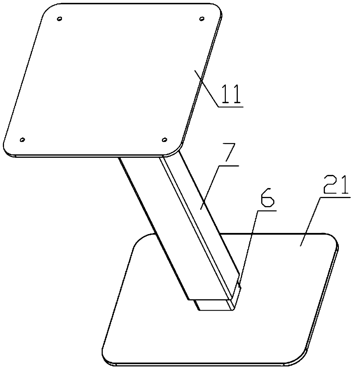
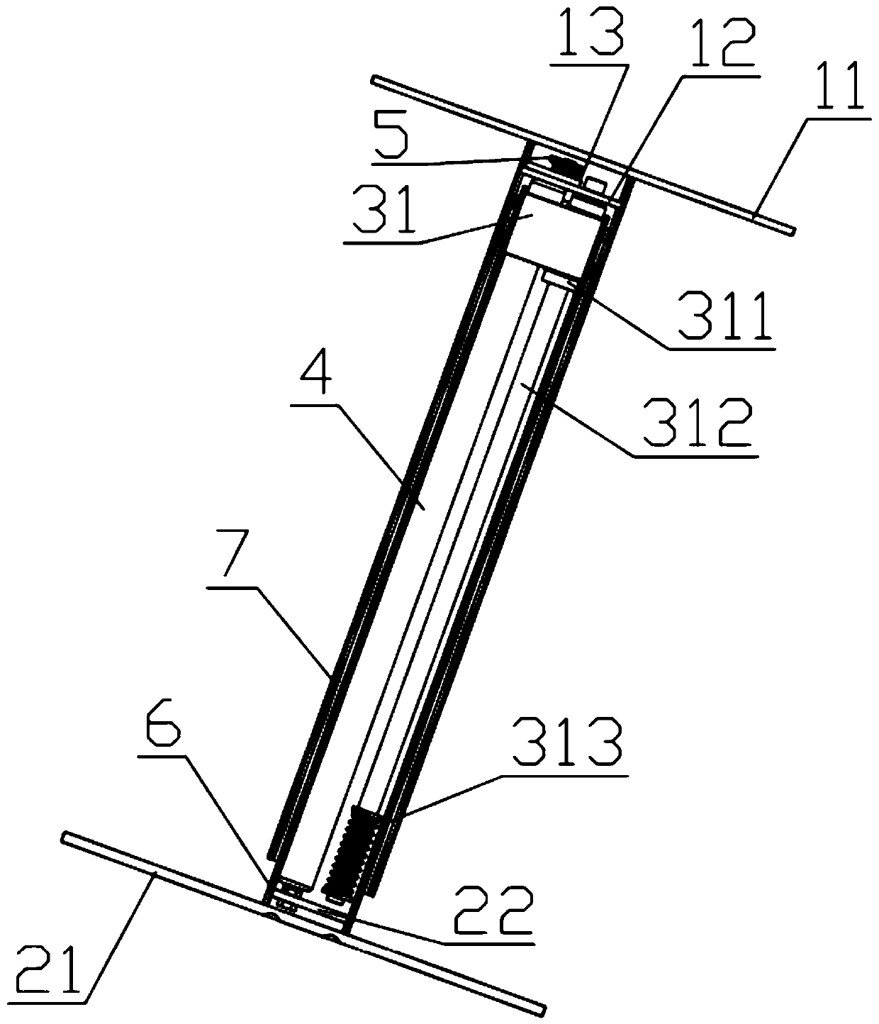
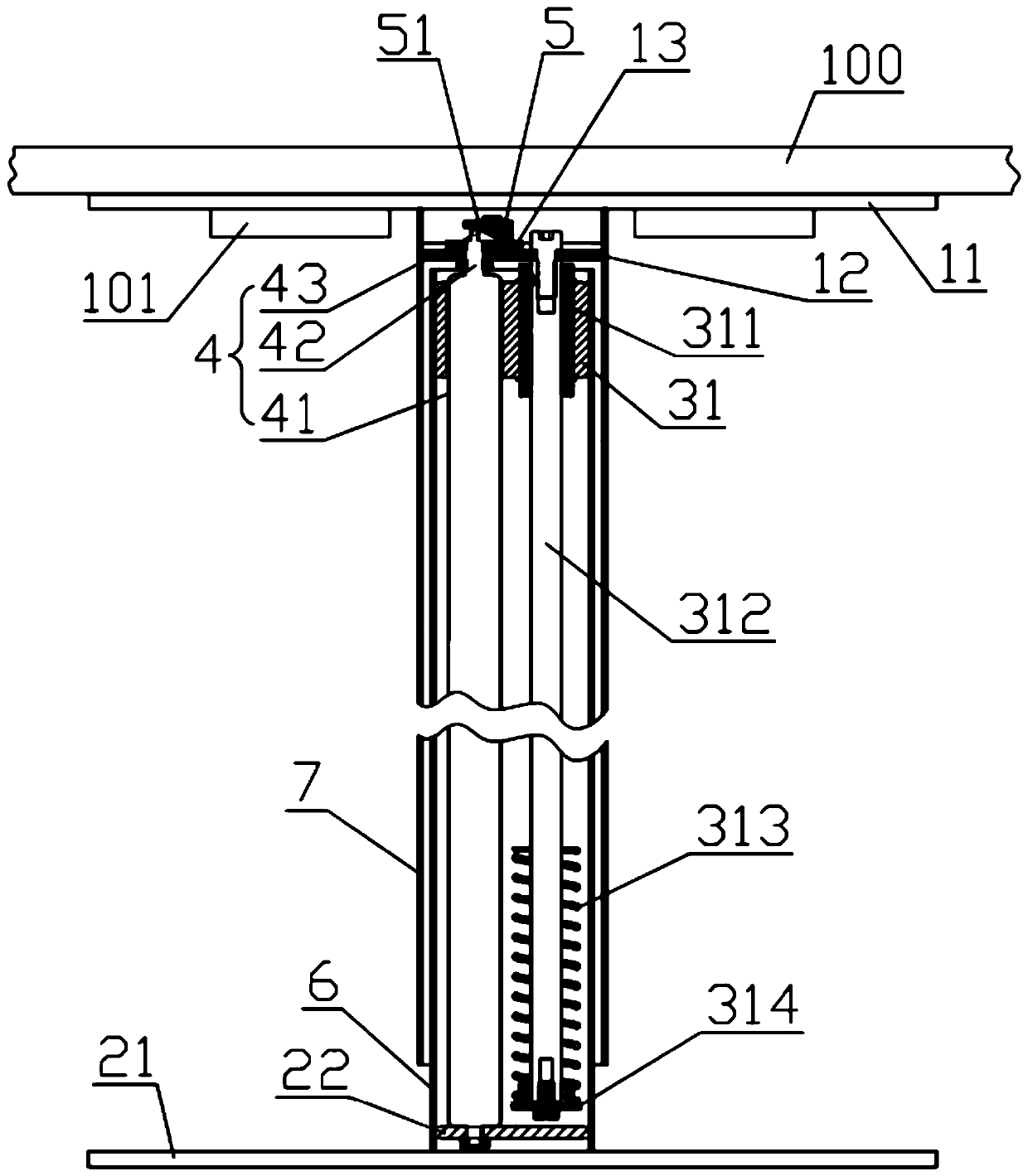
[0036] Such as Figures 1 to 3 As shown, the guide control mechanism of the pneumatic lift table according to one embodiment of the present invention includes a desktop support plate 11 , a lower bottom plate 21 , an upper fixing block 31 , a lockable gas spring 4 and a wedge switch 5 . The shape structure of the upper fixing block 31 can adopt a rectangular structure or a circular structure, and this embodiment adopts a rectangular structure. The upper fixed block 31 is fixedly sleeved on the upper end of the cylinder 41 of the lockable gas spring 4, the bottom of the cylinder 41 of the lockable gas spring 4 is connected with the lower connecting plate 22 and locked with a nut, the piston rod 42 of the lockable gas spring 4 The upper end portion is fixedly connected with an upper connecting plate 12 . A first linear bearing 311 is fixedly installed in the upper fixing block 31 , and a first linear optical axis 312 matched with it is placed in the first linear bearing 311 . ...

Embodiment 2

[0044] Such as Figure 7 and 8 As shown, the difference between Embodiment 2 and Embodiment 1 is that there are three sets of guides for the first linear optical axis 312 . Specifically, the first linear optical axis 312 is provided with three groups, the first linear bearing 311 matched with the first linear optical axis 312, and the first cylindrical coil spring 313 sleeved on the first linear optical axis 312 are all There are three groups, and on the upper fixing seat, the three groups of first linear bearings 311 are evenly distributed around the lockable gas spring 4 . In practical application, the guiding mechanism can also be two sets, that is, there are two sets of the first linear optical axis 312 , the first linear bearing 311 and the first cylindrical coil spring 313 . In this embodiment, the upper fixing block 31 adopts a circular structure, and the upper free end of the first cylindrical coil spring 313 is also clamped with a spring seat 314 . The first linear...

Embodiment 3

[0046] Such as Figure 11 , 12 As shown in and 15, the guide control mechanism of the pneumatic lifting table according to one embodiment of the present invention includes a desktop support plate 11, a lower bottom plate 21, an upper fixing block 31, a lower fixing block 32, an outer step tube 44, and a lockable gas spring 4. Wedge switch 5, outer sleeve 7, middle sleeve 8, inner sleeve 6, upper support rod 315 and lower support rod 325. In this embodiment, the outer structure of the upper fixing block 31 and the lower fixing block 32 adopts a cylindrical structure.

[0047]The cylinder barrel 41 of the lockable gas spring 4 is placed in the outer step tube 44, and the upper and lower ends of the outer step tube 44 are provided with steps, and the upper fixing block 31 and the lower fixing block 32 are respectively installed on the upper and lower ends of the outer step tube 44. superior. The upper fixed block 31 and the lower fixed block 32 installed on the two ends of the...


PUM


Abstract

The invention discloses a guide control mechanism for a pneumatic lifting table. The guide control mechanism comprises a table top supporting plate, a lower bottom plate, an upper fixing block, a lockable gas spring and a wedge-shaped switch, wherein the upper fixing block sleeves the lockable gas spring, the two ends of the lockable gas spring are connected with an upper connecting plate and a lower connecting plate respectively, and a first linear bearing sleeves a first linear unthreaded shaft and is installed in the upper fixing block. One end of the first linear unthreaded shaft is connected with the upper connecting plate, the other end of the first linear unthreaded shaft is provided with a first cylindrical spiral spring, an inner sleeve is connected with the lower bottom plate, and the lower connecting plate is covered with the inner sleeve. An outer sleeve is connected with the table top supporting plate, the upper connecting plate is covered with the outer sleeve, and the oblique wedge surface of the wedge-shaped switch can abut against a valve lift pin so that the outer sleeve can move relative to the inner sleeve in the direction away from or close to the lower bottomplate. The structure is compact, the guide precision is high, the lockable gas spring is smartly controlled by using the rotatable wedge-shaped switch, the cylindrical spiral springs solve the problemof impact generated when the lockable gas spring rises to the tail end, and due to the guide control mechanism, a table top more smoothly and steadily ascend and descend and is not likely to shake.

Description

technical field [0001] The invention relates to the technical field of household lifting equipment, and more specifically relates to a guiding control mechanism of a pneumatic lifting table. Background technique [0002] Pneumatic lifting mechanism is widely used in height-adjustable items such as beds, chairs, and tables. The main function is to move the load in a straight line through its own expansion and contraction. With the improvement of people's requirements for the quality of life, the home with lifting function will be developed by leaps and bounds. [0003] Pneumatic lifting tables on the market now generally use the inner and outer sleeves and the plane needle roller bearings matched with the inner sleeves to realize the guiding function. Because the inner and outer sleeves are extruded or rolled from aluminum or steel, the guide plane The accuracy is poor, the gap between the bushing and the needle roller is large, the desktop is easy to shake, and the size of ...

Claims


Application Information

Patent Timeline
Patent Type & Authority Applications(China)
IPC IPC(8): A47B9/10A47B13/02F16F9/02F16F9/56
CPCA47B9/10A47B13/023F16F9/0254F16F9/0281F16F2222/126
Inventor 张春勤
Owner 张春勤
Why Eureka
Try Eureka