
Monitoring camera based on computer technology

A monitoring camera and camera technology, applied in the computer field, can solve the problems that affect the shooting effect of the monitoring camera, easily adhere to debris such as dust, snow and leaves, and the lack of cleaning mechanism of the monitoring camera, so as to improve the user experience and cleaning effect Good, monitors a wide range of effects

Inactive Publication Date: 2019-07-23
XINXIANG UNIV
View PDF7 Cites 6 Cited by
  • Summary
  • Abstract
  • Description
  • Claims
  • Application Information

AI Technical Summary

Problems solved by technology

[0004] However, due to the lack of a corresponding cleaning mechanism for the surveillance camera, dust, snow, leaves and other debris are easily adhered to the surface of the surveillance camera during use, and the continuous accumulation of debris will affect the shooting effect of the surveillance camera.

Method used


Image

  • Monitoring camera based on computer technology
  • Monitoring camera based on computer technology
  • Monitoring camera based on computer technology

Examples


Embodiment 1

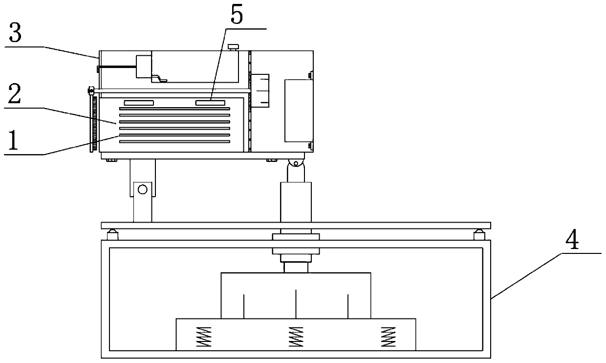
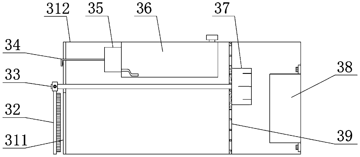
[0024] see figure 1 and figure 2 , the present invention provides a technical solution: a monitoring camera based on computer technology, comprising a camera body 2, the outer surface of the camera body 2 is provided with cooling fins 1, the top of the camera body 2 is provided with a cooling through hole 5, the camera body The outer side of 2 is provided with cleaning mechanism 3, and cleaning mechanism 3 comprises casing 312, and one end of casing 312 is provided with the glass panel 311 corresponding with camera body 2, is provided with the first corresponding with camera body 2 on the glass panel 311. Limiting through holes, one side of the glass panel 311 is provided with a cleaning brush plate 32, one side of the camera body 2 is provided with a partition 39, and the top of the partition 39 is provided with a first motor 37, and the first motor 37 is connected to the cleaning brush plate The joint of 32 is provided with transmission rod 33;

[0025] In order to make t...

Embodiment 2

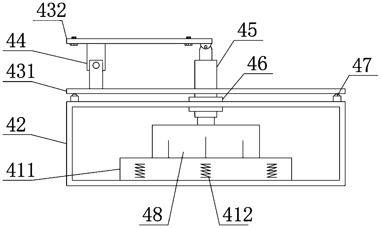
[0028] see Figure 1-Figure 4 , on the basis of Embodiment 1, in order to enrich the functions of the monitoring camera, in this embodiment, preferably, a position adjustment mechanism 4 is provided below the camera body 2, and the position adjustment mechanism 4 includes a support base 42, and the support base 42 The top of the first support plate 431 is provided with a first support plate 431, and the connection between the first support plate 431 and the support base 42 is provided with an electric telescopic rod 45. The top of the first support plate 431 is movably connected with a second support plate 432 through a connector 44. The second support plate 432 can rotate around the first support plate 431 through the connector 44, and the second support plate 432 is fixed on the box body 312 by the screws at both ends of the lower surface. The rod 45 stretches or shrinks, and at this moment, the camera end of the camera body 2 sinks or rises correspondingly, so that the user...


PUM


Abstract

The invention discloses a monitoring camera based on a computer technology, belongs to the technical field of computers, the camera comprises a camera body, heat dissipation fins are arranged on the outer surface of the camera body. A heat dissipation through hole is formed in the top end of the camera body; a cleaning mechanism is arranged on the outer side of the camera body and comprises a boxbody, a glass panel corresponding to the camera body is arranged at one end of the box body, a cleaning brush plate is arranged on one side of the glass panel, a partition plate is arranged on one side of the camera body, and a first motor is arranged at the top end of the partition plate. A cleaning mechanism is arranged on the monitoring camera; a user can clean sundries on the camera body through the cleaning brush plate on the cleaning mechanism, so that the shooting effect of the monitoring camera is prevented from being influenced by continuous accumulation of the sundries, and then theuser can supply water to the cleaning brush plate through the water pump and the water supply pipe, so that the cleaning effect of the cleaning brush plate is better.

Description

technical field [0001] The invention belongs to the field of computer technology, and in particular relates to a monitoring camera based on computer technology. Background technique [0002] Camera, also known as computer camera, computer eye and electronic eye, is a video input device, which is widely used in video conferencing, telemedicine and real-time monitoring. [0003] Chinese patent (publication number CN204810397U) discloses a monitoring camera for the Internet of Things, including a monitoring camera body, the monitoring camera body includes a housing, a computer and a mobile phone terminal, and the housing is equipped with a camera, a central processing unit, and an information storage device. , storage battery, signal sensor and remote control switch. There is a charging socket at the bottom of the storage battery. The signal sensor is connected to the central processing unit through wire tubes. The information memory is connected to the central processing unit....

Claims


Application Information

Patent Timeline
Patent Type & Authority Applications(China)
IPC IPC(8): H04N5/225H04N7/18F16M11/26F16M11/04F16F15/04B08B1/00
CPCH04N7/18F16M11/26F16M11/04F16F15/04H04N23/50B08B1/12
Inventor 王芸陈晓前王晓洁
Owner XINXIANG UNIV
Learn More