Mine sweeping device

A technology of mine-sweeping device and mine-sweeping projectile, which is applied to defensive devices, offensive equipment, etc., can solve the problems of environmental damage, high power of cloud explosive projectiles, and kill and damage, and achieves the effect of less environmental damage and widening the width of mine-sweeping channels.

Pending Publication Date: 2019-07-23
NAT UNIV OF DEFENSE TECH
View PDF0 Cites 3 Cited by
  • Summary
  • Abstract
  • Description
  • Claims
  • Application Information

AI Technical Summary

Problems solved by technology

2: More than 100KP high-intensity shock waves, according to theoretical calculations: 30-40KP shock waves will cause minor injuries (such as eardrum rupture); 40-60KP shock waves will cause moderate damage (severe damage to hearing, vision and other organs, internal bleeding, fractures, etc.) ; The shock wave of 60-100KP will cause serious damage (internal organ rupture, severe bleeding, etc.); the shock wave of >100KP will cause extremely high biological mortality
For a long time, although people have the desire to use cloud explosives for minesweeping, due to cloud explosive minesweeping, when the operator is too close to the cloud explosive bomb, once the cloud explosive bomb explodes by mistake, it will cause very serious consequences; If a rocket launcher is used to launch cloud bombs, there are still mine clearances that are not suitable for complex terrain such as steep terrain, the road ahead is curved, there are obstacles, and the line of sight is blocked; the cloud bombs are powerful and the environment is severely damaged, which seriously restricts The application of cloud explosives in minesweeping, especially its use in civilian fields with stricter environmental protection requirements

Method used


Image

  • Mine sweeping device
  • Mine sweeping device
  • Mine sweeping device

Examples


Embodiment 1

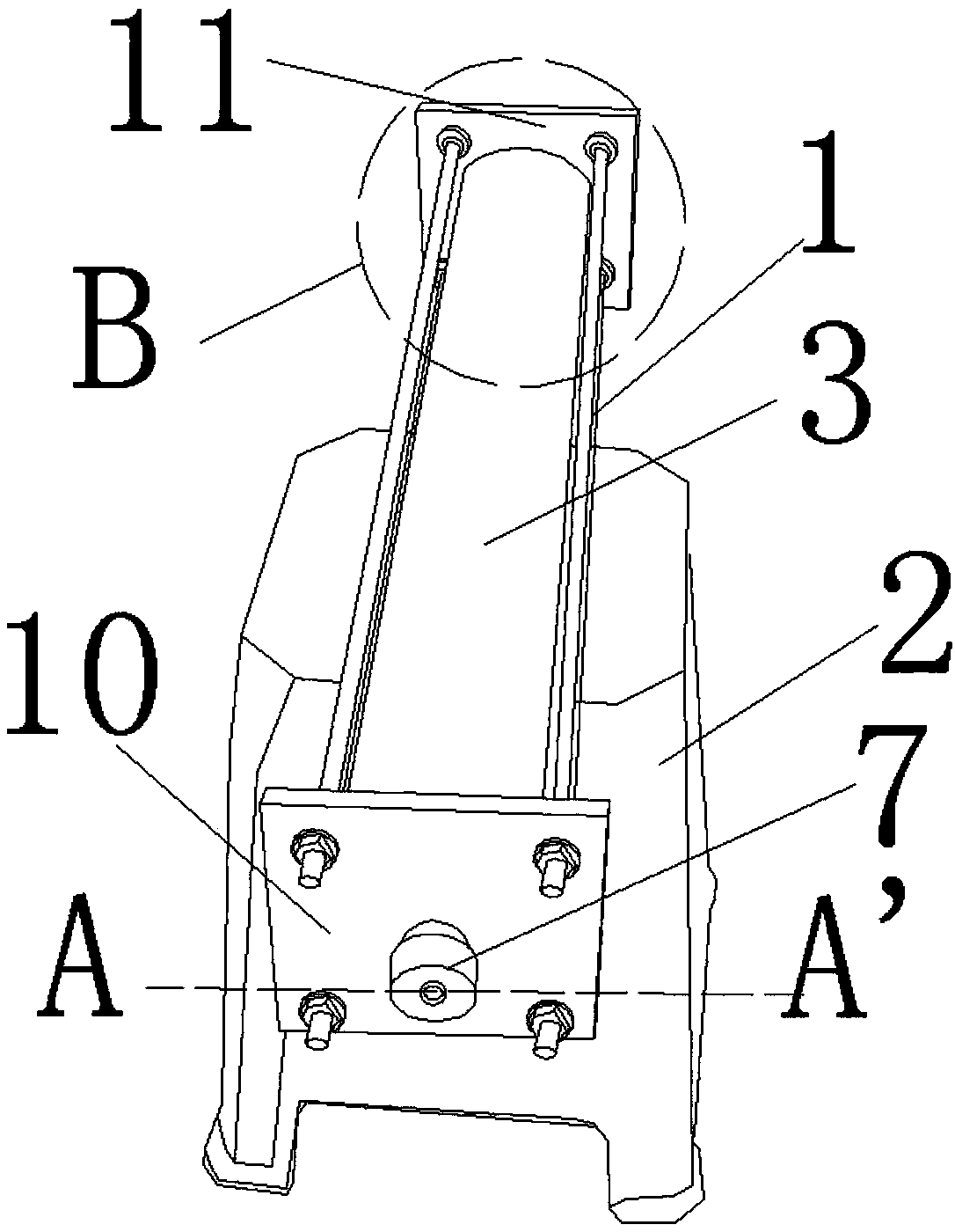
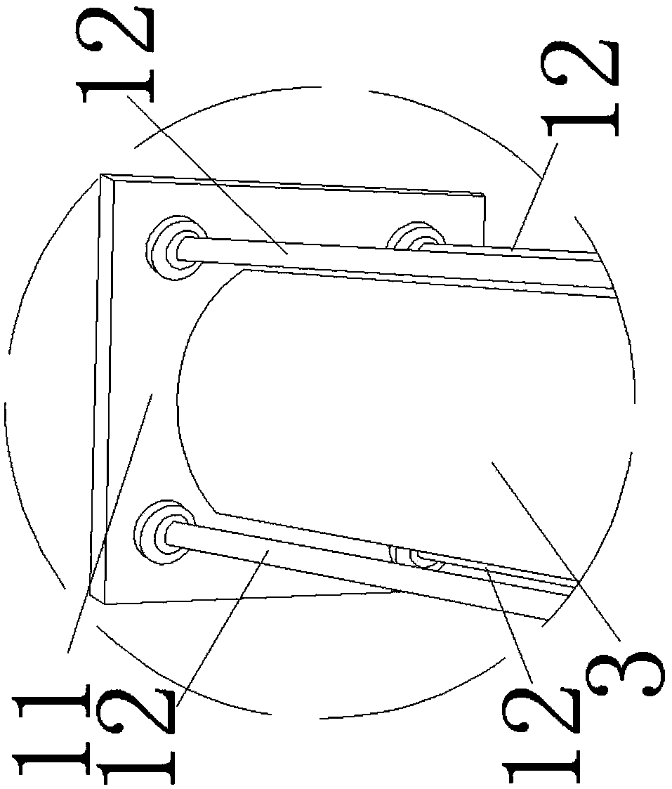
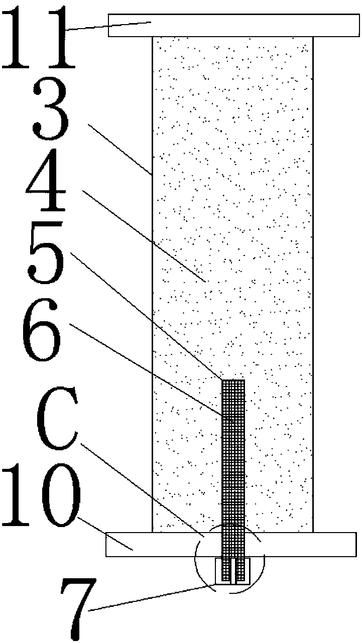
[0065] Example 1. A kind of cloud explosion mine-sweeping bomb is characterized in that: comprise fixed bracket 1, the detonating device 9 that is installed on the fixed bracket 1, the expansion part, the cloud explosion part, the fixed bracket 1 is installed on the support frame 2; The cloud explosion part includes outer Cartridge 3, cloud explosive agent 4 is housed in outer cartridge 3; Explosion expansion part includes inner cartridge 5, and expansion explosive 6 is housed in inner cartridge 5; Block cap 7 is installed on the inner cartridge 5, and block cap 7 is provided with Detonator hole 8, detonator 9 is housed in the detonator hole 8; Inner cartridge 5 is inserted in the outer cartridge 3.

[0066] The outer cartridge 3 is in the shape of an elliptical column, and the central axis of the outer cartridge 3 is parallel to the ground. With this technical solution, the distance and stability of the shock wave generated by the explosion propagating on the ground along th...

Embodiment 2

[0081] Example 2. The difference between this embodiment and Embodiment 1 is that the height of the support frame 2 is 100 cm, and the outer cartridge is in the shape of an ellipse. The length of outer cartridge 3 is 100cm, and the major axis length of cross section is 150mm, and the minor axis length is 70mm, and wall thickness is 3.0mm, and the weight of cloud blasting agent is 8.5kg. The length of the inner cartridge is 48cm, the outer diameter is 25mm, the wall thickness is 3.0mm, and the weight of the expansion agent is 300g. The major axis and central axis of the outer cartridge 3 are parallel to the ground. The central axes of the outer cartridge 3 and the inner cartridge 5 are coincident. With this technical scheme, the spraying range of the cloud blasting agent in the horizontal direction is larger, and the shock wave generated by the explosion can act on the ground with as large an area as possible.

[0082] After described detonating device 5 detonates the explosi...

Embodiment 3

[0083] Example 3. Such as Figure 6-10 As shown, a mine-sweeping device, 10 cloud-burst mine-sweeping bombs are loaded on the low-altitude aircraft, a total of 10, weighing about 80kg. The cloud-explosive mine-sweeping bomb is transported to the mine-sweeping channel by the low-altitude aircraft and the central axis of the outer cartridge 3 of the cloud-explosive mine-sweeping bomb is maintained at a certain angle with the central axis of the mine-sweeping channel. By adopting the technical scheme, it can be adapted to the terrain with steep terrain. At present, civil low-altitude aircraft is developing rapidly, such as the plant protection aircraft Z5 of the 60th Institute of the General Staff, with a load of up to 80 kg. The flying height of the low-altitude aircraft is 5-20 meters.

[0084] Described low-altitude aircraft comprises low-altitude aircraft frame 13, and low-altitude aircraft frame 13 is provided with positioning system module 14, camera 15, magnetic compass...


PUM

PropertyMeasurementUnit
Heightaaaaaaaaaa
Lengthaaaaaaaaaa
Outer diameteraaaaaaaaaa

Abstract

The invention discloses a mine sweeping device, and belongs to the field of mine blasting and barrier breaking. The mine sweeping device comprises a low-altitude aircraft and a fuel air explosive minesweeping bomb, wherein the fuel air explosive mine sweeping bomb comprises a fixing support, an initiating device, a mine booster part and a fuel air explosive part; the initiating device, the mine booster part and the fuel air explosive part are arranged on the fixing support; the fixing support is arranged on a supporting frame; the fuel air explosive part comprises an outer cartridge; the outer cartridge is filled with fuel air explosive agents; the mine booster part comprises an inner cartridge; the inner cartridge is filled with mine boosters; a cap is arranged on the inner cartridge; adetonator hole is formed in the cap; the initiating device is arranged in the detonator hole; and the inner cartridge is inserted into the outer cartridge. According to the mine sweeping device, the fuel air explosive mine sweeping bomb is conveyed to a mine channel to be swept through the low-altitude aircraft, and the central axis of the outer cartridge of the fuel air explosive mine sweeping bomb is kept to be at a certain angle with the central axis of the mine channel to be swept. The mine sweeping device has the characteristics of large mine sweeping area, small damage to environment andconvenient operation.

Description

technical field [0001] The invention relates to the field of mine blasting and barrier breaking, in particular to a mine-sweeping device for international humanitarianism. Background technique [0002] Landmines are explosive weapons that can be placed underground or on the ground in various ways and means to form explosive obstacles, which can effectively kill and injure the enemy's vital forces, destroy their technical weapons, and prevent the enemy from acting. During the conflict, all parties involved in the war used a large number of landmines. The resulting problem of indiscriminate use of landmines led to the desertion of large areas of land in the belligerent countries and the displacement of people, which seriously affected economic construction and people's lives. With the strengthening of my country's comprehensive national strength The country has gradually increased humanitarian assistance to mine-affected countries. Therefore, it is urgently required to improve a...

Claims


Application Information

Patent Timeline
IPC IPC(8): F41H11/12
CPCF41H11/12
Inventor 吴克刚汪庆桃宋殿义文晓宇陈志阳
Owner NAT UNIV OF DEFENSE TECH
Why Eureka
Try Eureka