
A Serpentine Rapid Viscosity Reduction Device Based on Coupling Effect in Oilfield Wellhead

A serpentine and viscosity-reducing technology, which is applied in the pipeline system, gas/liquid distribution and storage, mechanical equipment, etc., can solve the problems of unfavorable energy saving, heavy oil viscosity reduction and high energy consumption, etc., to promote full contact and fusion, Realize the effect of reducing viscosity and ensuring transportation

Active Publication Date: 2020-09-08
HEILONGJIANG LANDE ULTRASONIC TECH CO LTD
View PDF9 Cites 0 Cited by
  • Summary
  • Abstract
  • Description
  • Claims
  • Application Information

AI Technical Summary

Problems solved by technology

However, the equipment consumes too much energy to reduce the viscosity of heavy oil by heating, which is not conducive to energy saving

Method used


Image

  • A Serpentine Rapid Viscosity Reduction Device Based on Coupling Effect in Oilfield Wellhead
  • A Serpentine Rapid Viscosity Reduction Device Based on Coupling Effect in Oilfield Wellhead
  • A Serpentine Rapid Viscosity Reduction Device Based on Coupling Effect in Oilfield Wellhead

Examples


specific Embodiment approach 1

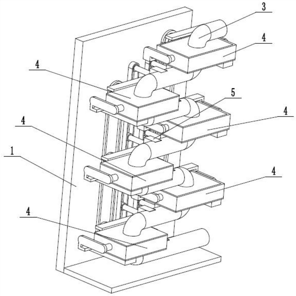
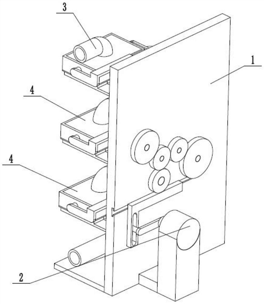
[0032] Such as Figure 1 to Figure 13As shown, a serpentine rapid viscosity reduction device at the wellhead of an oilfield based on coupling effects, including a fixed base 1, a driver 2, a serpentine transportation pipeline 3, multiple extrusion viscosity reducers 4 and multiple stirring and mixing viscosity reducers 5. The plurality of extrusion-propelled viscosity reducers 4 are all fixedly connected to the fixed base 1, and the serpentine transportation pipeline 3 is uniformly fixedly connected and communicated with multiple extrusion-propelled viscosity reducers 4, and the multiple extrusion-propelled The viscosity reducers 4 are connected by a toothed transmission belt, and multiple agitating and mixing viscosity reducers 5 are uniformly and fixedly connected to the serpentine transportation pipeline 3, and multiple agitating and mixing viscosity reducers 5 are connected by a toothed transmission belt , the driver 2 is fixedly connected to the fixed base 1, and the driv...

specific Embodiment approach 2

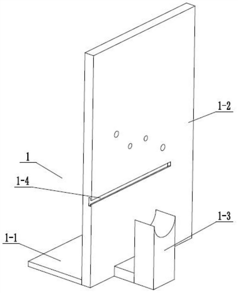
[0034] Such as Figure 1 to Figure 13 As shown, this embodiment further describes the first embodiment, the fixed base 1 includes a bottom plate 1-1, a riser 1-2, a motor fixing seat 1-3 and a T-shaped sliding groove 1-4, the described The vertical plate 1-2 is fixedly connected to the front end of the base plate 1-1, the motor holder 1-3 is fixedly connected to the front end of the vertical plate 1-2, and the T-shaped sliding groove 1-4 is arranged on the front end of the vertical plate 1-2.

specific Embodiment approach 3

[0036] Such as Figure 1 to Figure 13 As shown, this embodiment further describes the second embodiment, the driver 2 includes a servo drive motor 2-1, a drive connecting rod 2-2, a drive rod 2-3, a drive chute 2-4, and an L-shaped drive Rack 2-5, T-shaped slider 2-6, main drive gear 2-7, main drive shaft 2-8, right mixed drive gear 2-9, left mixed drive gear 2-10, right extrusion drive gear 2 -11 and the left extrusion drive gear 2-12, the servo drive motor 2-1 is fixedly connected on the motor holder 1-3, and one end of the drive connecting rod 2-2 is fixedly connected on the output shaft of the servo drive motor 2-1 , the other end of the driving connecting rod 2-2 is fixedly connected to the driving rod 2-3, and the driving rod 2-3 is slidably connected in the driving chute 2-4, and is arranged on the right end of the L-shaped driving rack 2-5 through front and rear, L The rear end of the L-shaped driving rack 2-5 is fixedly connected to the T-shaped slide block 2-6, and ...


PUM


Abstract

The invention relates to the field of oil viscosity reduction, in particular to an oil field well mouth S-shaped rapid viscosity reduction device based on the coupling function. A fixing base, a driver, an S-shaped transportation pipeline, a plurality of extrusion pushing viscosity reducers and a plurality of stirring mixing viscosity reducers are included. The multiple extrusion pushing viscosityreducers are fixedly connected to the fixing base. The S-shaped transportation pipeline is evenly and fixedly connected and communicates with the multiple extrusion pushing viscosity reducers. The multiple extrusion pushing viscosity reducers are in belt transmission connection through a tooth-shaped transmission belt. The oil field well mouth S-shaped rapid viscosity reduction device has the beneficial effects that through transportation of the S-shaped pipeline, the transportation distance of the S-shaped pipeline is increased, in the transportation process, sufficient contact and fusion between thickened oil and a viscosity reduction mixing agent are promoted through mixing and stirring, and accordingly, viscosity of the thickened oil is reduced; and to avoid the long thickened oil transportation stroke and large resistance, relay type extrusion pushing is adopted, thickened oil transportation is guaranteed, and accordingly thickened oil viscosity reduction is achieved.

Description

technical field [0001] The invention relates to the field of petroleum viscosity-reducing transportation, in particular to a serpentine rapid viscosity-reducing device at the wellhead of an oil field based on a coupling effect. Background technique [0002] The patent number is CN201510520823.1, which discloses a heavy oil viscosity reducing device, including a frame, a rotating device, a stirring device, a heating device, a holding device and an oil separating device. The frame is provided with a first sealing ring, a first sealing ring, the first filter net, the second filter net, the collecting hopper and the supporting ring, the rotating device includes the motor, the first support, the first rotating shaft, the first fixed rod and the first gear, the stirring device includes the first supporting rod, the second The rotating shaft, the second gear, the stirring rod and the third filter screen, the heating device includes a heating rod, a heat conduction frame, a first fi...

Claims


Application Information

Patent Timeline
Patent Type & Authority Patents(China)
IPC IPC(8): F17D1/17F17D1/16
CPCF17D1/16F17D1/17
Inventor 赵宪忠赵蓉杜超曾大开武明杰关丽娜黄滨
Owner HEILONGJIANG LANDE ULTRASONIC TECH CO LTD
Learn More