Oil field well mouth S-shaped rapid viscosity reduction device based on coupling function
A serpentine, viscosity-reducing technology, which is applied in pipeline systems, mechanical equipment, gas/liquid distribution and storage, etc., can solve the problems of unfavorable energy saving, heavy oil viscosity reduction and high energy consumption, and achieve full contact and fusion, Realize the effect of reducing viscosity and ensuring transportation
- Summary
- Abstract
- Description
- Claims
- Application Information
AI Technical Summary
Problems solved by technology
Method used
Image
Examples
specific Embodiment approach 1
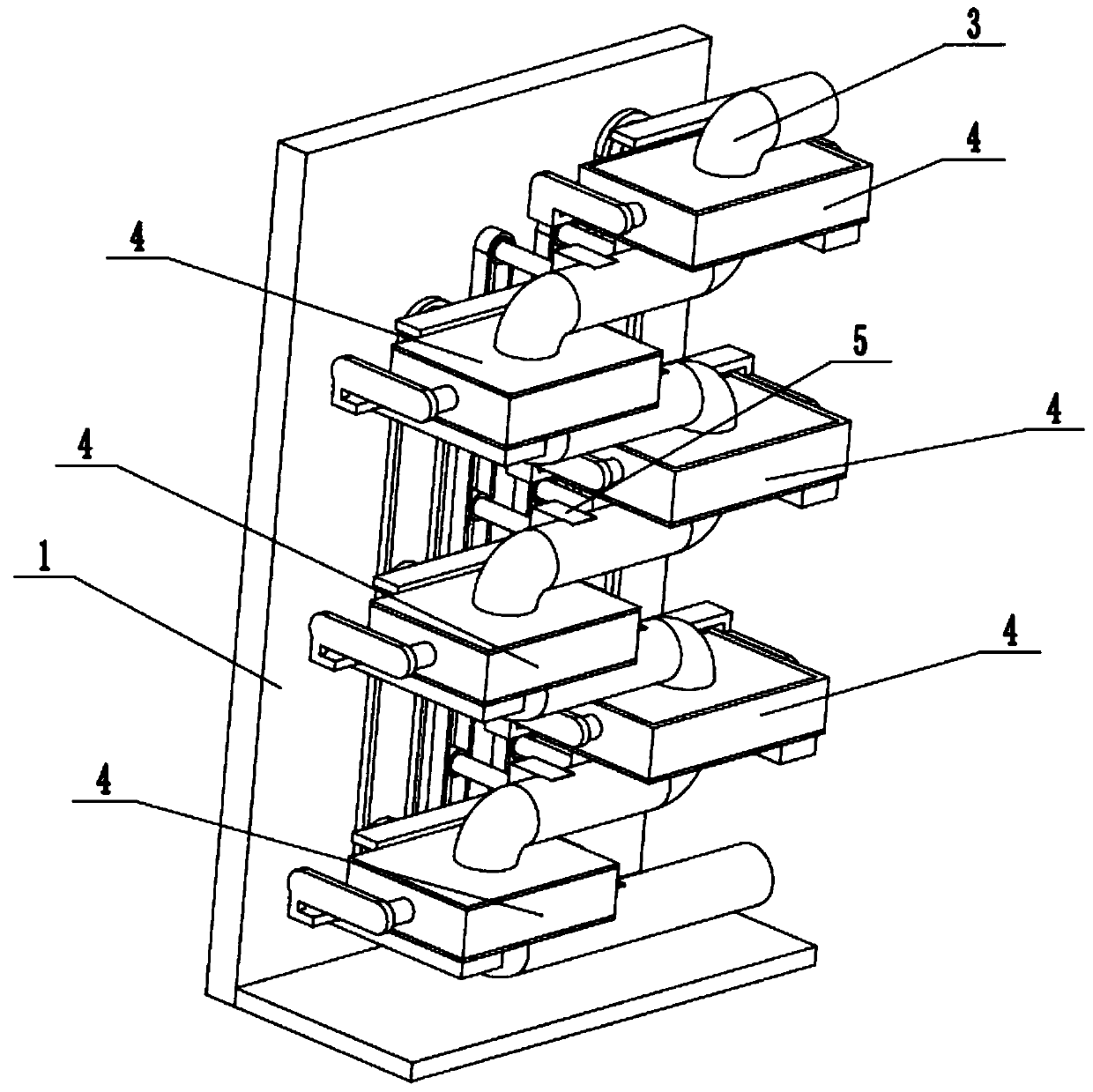
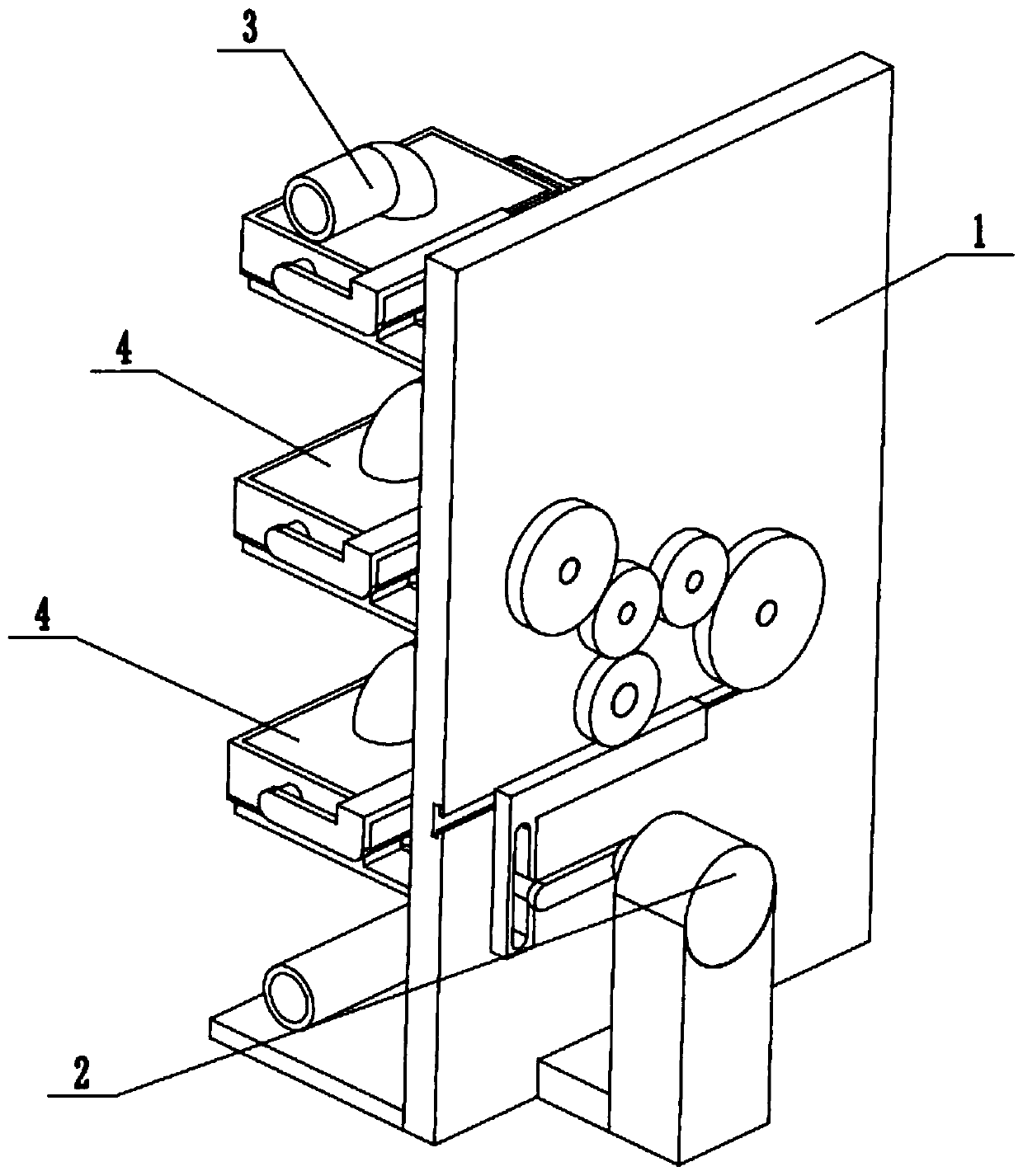
[0032] Such as Figure 1 to Figure 13As shown, a serpentine rapid viscosity reduction device at the wellhead of an oilfield based on coupling effects, including a fixed base 1, a driver 2, a serpentine transportation pipeline 3, multiple extrusion viscosity reducers 4 and multiple stirring and mixing viscosity reducers 5. The plurality of extrusion-propelled viscosity reducers 4 are all fixedly connected to the fixed base 1, and the serpentine transportation pipeline 3 is uniformly fixedly connected and communicated with multiple extrusion-propelled viscosity reducers 4, and the multiple extrusion-propelled The viscosity reducers 4 are connected by a toothed transmission belt, and multiple agitating and mixing viscosity reducers 5 are uniformly and fixedly connected to the serpentine transportation pipeline 3, and multiple agitating and mixing viscosity reducers 5 are connected by a toothed transmission belt , the driver 2 is fixedly connected to the fixed base 1, and the driv...
specific Embodiment approach 2
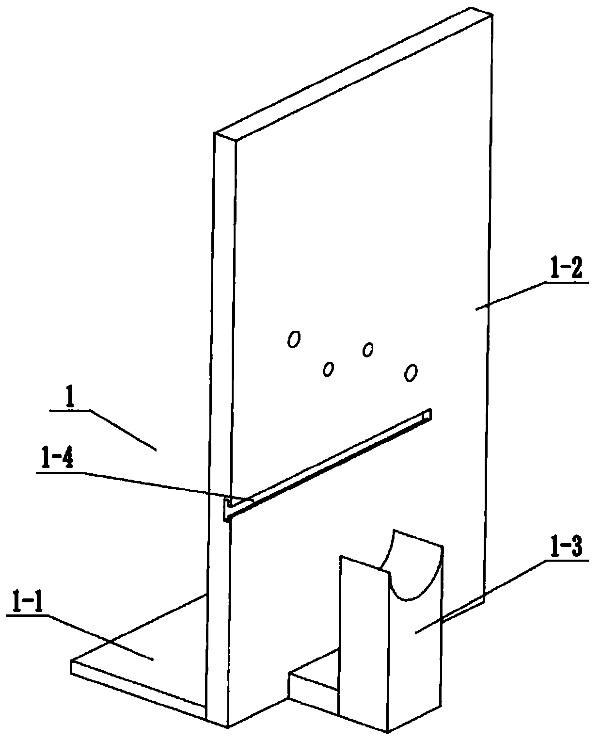
[0034] Such as Figure 1 to Figure 13 As shown, this embodiment further describes the first embodiment, the fixed base 1 includes a bottom plate 1-1, a riser 1-2, a motor fixing seat 1-3 and a T-shaped sliding groove 1-4, the described The vertical plate 1-2 is fixedly connected to the front end of the base plate 1-1, the motor holder 1-3 is fixedly connected to the front end of the vertical plate 1-2, and the T-shaped sliding groove 1-4 is arranged on the front end of the vertical plate 1-2.
specific Embodiment approach 3
[0036] Such as Figure 1 to Figure 13 As shown, this embodiment further describes the second embodiment, the driver 2 includes a servo drive motor 2-1, a drive connecting rod 2-2, a drive rod 2-3, a drive chute 2-4, and an L-shaped drive Rack 2-5, T-shaped slider 2-6, main drive gear 2-7, main drive shaft 2-8, right mixed drive gear 2-9, left mixed drive gear 2-10, right extrusion drive gear 2 -11 and the left extrusion drive gear 2-12, the servo drive motor 2-1 is fixedly connected on the motor holder 1-3, and one end of the drive connecting rod 2-2 is fixedly connected on the output shaft of the servo drive motor 2-1 , the other end of the driving connecting rod 2-2 is fixedly connected to the driving rod 2-3, and the driving rod 2-3 is slidably connected in the driving chute 2-4, and is arranged on the right end of the L-shaped driving rack 2-5 through front and rear, L The rear end of the L-shaped driving rack 2-5 is fixedly connected to the T-shaped slide block 2-6, and ...
PUM
 Abstract
Description
Claims
Application Information
 - R&D
- Intellectual Property
- Life Sciences
- Materials
- Tech Scout
- Unparalleled Data Quality
- Higher Quality Content
- 60% Fewer Hallucinations
Browse by: Latest US Patents, China's latest patents, Technical Efficacy Thesaurus, Application Domain, Technology Topic, Popular Technical Reports.
© 2025 PatSnap. All rights reserved.Legal|Privacy policy|Modern Slavery Act Transparency Statement|Sitemap|About US| Contact US: help@patsnap.com


