Lifting type energy-saving dust removal and unreeling mechanism with 360-degree sweeping function
A technology of unwinding mechanism and lifting mechanism, which is applied in textiles and papermaking, weft knitting, knitting, etc. It can solve the problems of loud noise in the workplace, cumbersome installation, and inability to carry out all-round dust removal, so as to reduce the frequency of downtime and reduce the The effect of defective products
- Summary
- Abstract
- Description
- Claims
- Application Information
AI Technical Summary
Problems solved by technology
Method used
Image

Examples
Embodiment 1
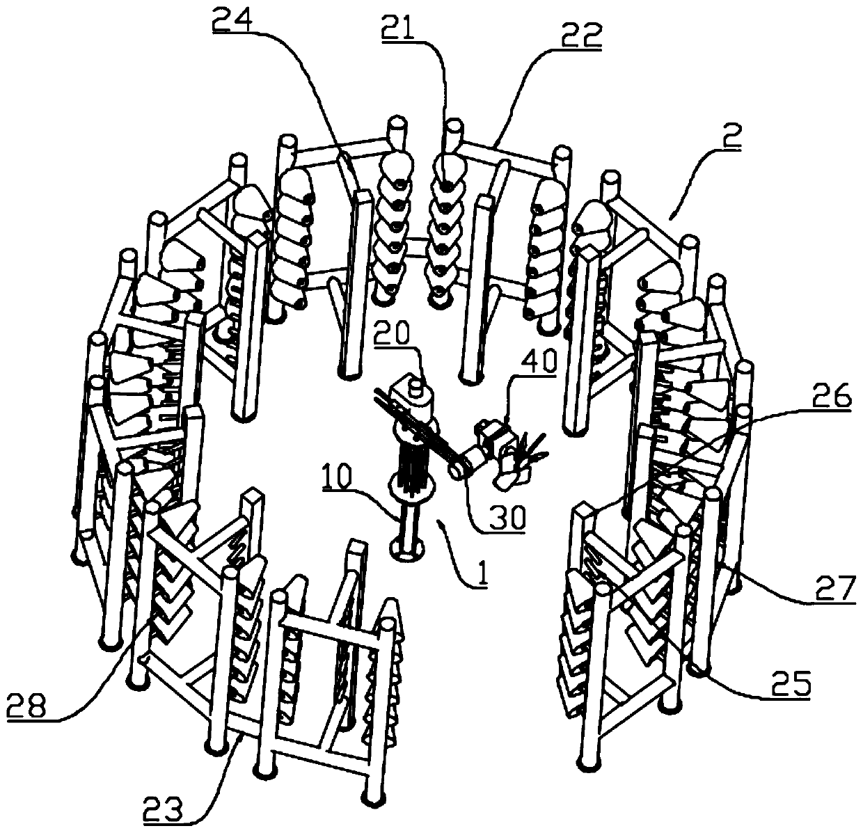
[0041] Such as figure 1 As shown, the energy-saving dedusting and unwinding mechanism for lifting 360-degree cleaning includes a fan cleaning device 1 and a creel 2. The unwinding mechanism is the creel 2. Large-scale cleaning of yarn wool and dust. It is easier to clean yarn wool when it falls, but it is difficult to clean it when it accumulates for a long time.
[0042] Yarn bobbins 21 are placed on the creel 2, and are decomposed into yarns that are transported to the knitting machine through the yarn channel. The fan cleaning device 1 is installed at the center of the creel 2, and the creel 2 surrounds the Around the fan cleaning device 1, the creel 2 can be arranged in a circular, square or other required shape,
[0043] The fan cleaning device 1 includes a lifting mechanism 10 , a central rotating mechanism 20 , a fan supporting mechanism 30 , a blowing mechanism 40 , and a controller 50 .
[0044] Such as figure 1 As shown, the creel 2 includes a bobbin 21, a cross b...
Embodiment 2
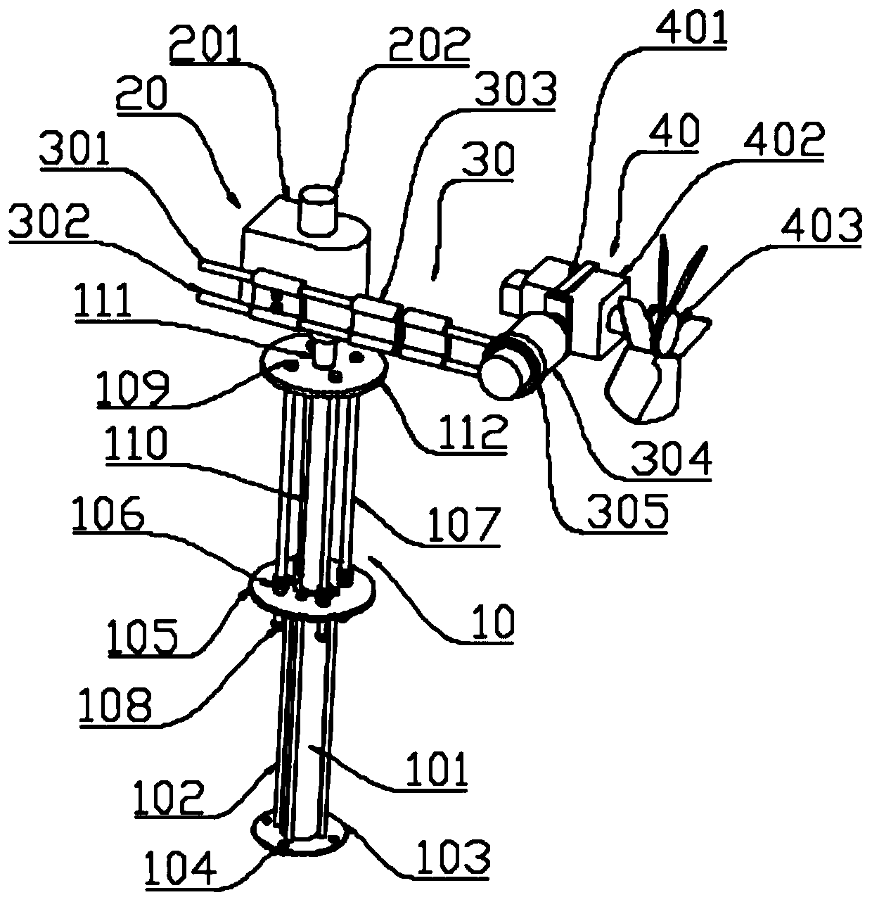
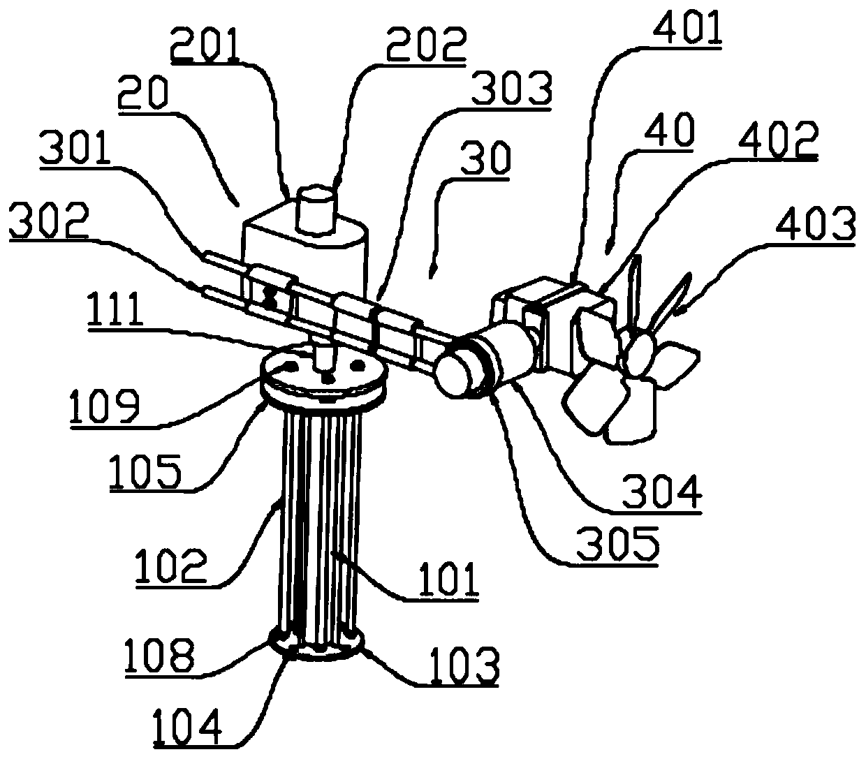
[0053] Other parts are the same as Embodiment 1, and the lifting mechanism 10 is a hydraulic transmission mechanism, such as figure 2 , 3 As shown, the lifting mechanism 10 can be lifted and lowered in the vertical direction. The lifting mechanism 10 is fixed on the ground, and the upper part is connected with the central rotating mechanism 20, which can drive the central rotating mechanism 20 to move vertically up and down. The lifting mechanism 10 includes a platen 103, hydraulic cylinder, first flange 105, second flange 112, the platen 103 is fixed on the ground by a plurality of screws 104, the bottom of the hydraulic cylinder is installed in the center of the platen 103, the The hydraulic cylinder is installed vertically, the liquid inlet of the hydraulic cylinder is connected to the external hydraulic station, the top of the hydraulic cylinder is fixedly connected by the first flange 105, and the first flange 105 is connected to the The platen 103 is parallel and suppo...
Embodiment 3
[0055] The other parts are the same as the first embodiment, the lifting mechanism 10 is a screw drive mechanism, and the screw drive mechanism includes a casing, a second motor, a gear set, a screw mandrel, a nut and a drive rod. The second motor is a stepping motor, which forms a reduction mechanism with the gear set, the motor shaft of the second motor is connected with the first gear of the gear set, and the second gear of the gear set meshes with the first gear. The screw mandrel is contained in the outer jacket, and the lower end of the screw mandrel is fixed with a second gear. The screw rod is threadedly connected with the nut positioned at its lower end, and a transmission rod is fixed on the top of the nut, and the transmission rod is sleeved on the outside of the screw rod, and the upper end of the transmission rod and the mandrel 205 are fixed with screws. The second motor drives the screw to rotate through the gear set, and drives the mandrel 205 to move up and do...
PUM
 Abstract
Description
Claims
Application Information
 - R&D
- Intellectual Property
- Life Sciences
- Materials
- Tech Scout
- Unparalleled Data Quality
- Higher Quality Content
- 60% Fewer Hallucinations
Browse by: Latest US Patents, China's latest patents, Technical Efficacy Thesaurus, Application Domain, Technology Topic, Popular Technical Reports.
© 2025 PatSnap. All rights reserved.Legal|Privacy policy|Modern Slavery Act Transparency Statement|Sitemap|About US| Contact US: help@patsnap.com