Vacuum interlayer fractionation column and fractionation device
A technology of vacuum interlayer and fractionation device, which is applied in the direction of fractionation, etc., can solve problems such as faults, gas outside the instrument flowing back into the fractionation device, etc., and achieve the effect of high fractionation efficiency, stable fractionation efficiency, and easy cleaning
- Summary
- Abstract
- Description
- Claims
- Application Information
AI Technical Summary
Problems solved by technology
Method used
Image
Examples
Embodiment 1
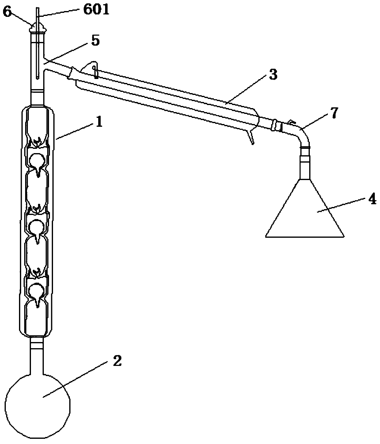
[0025] Embodiment 1: as figure 1 As shown, the vacuum interlayer fractionation column 1 comprises an air outlet 101, an air inlet 102, an outer tube 103, an inner column 104, several thorn-type draw-in grooves 105 and several spherical glass plugs 106, and the bottom end of the inner column 104 faces toward the An air inlet 102 is provided on the outside; the top of the inner column 104 extends outwards and a connecting pipe 107 is provided, and one side of the connecting pipe 107 is provided with an air outlet 101; the outer pipe 103 is located in the inner column 104 The outer layer of the outer tube 103 surrounds the inner column 104 and seals the bottom and top ends of the inner column 104 so that there is a gap between the inner wall of the outer tube 103 and the outer wall of the inner column 104 Leave a gap as a vacuum interlayer; the inner wall of the inner column 104 is provided with several thorn-shaped clamping grooves 105; the inner column 104 is recessed inwardly ...
Embodiment 2
[0026] Embodiment 2: as figure 2As shown, the fractionation device comprises a retort 2, a vacuum interlayer fractionation column 1, a condensation pipe 3 and a receiver 4, the upper end of the retort 2 is detachably connected with the vacuum interlayer fractionation column 1, and the vacuum interlayer fractionation column The upper end of 1 is detachably connected with a fractionation head 5, and one end of the outward extension of the fractionation head 5 is detachably connected with a condensation pipe 3, and the lower end of the condensation pipe 3 is detachably connected with a receiver 4; the fractionation head 5 The top end plug has a bottle stopper 6 with a thermometer 601, and the thermometer 601 is inserted into the fractionating head 5 through the bottle stopper 6; the condensing pipe 3 is also provided with a vacuum connecting pipe 7, and the lower end of the condensing pipe 3 passes through The vacuum connecting pipe 7 is detachably connected to the receiver 4; t...
Embodiment 3
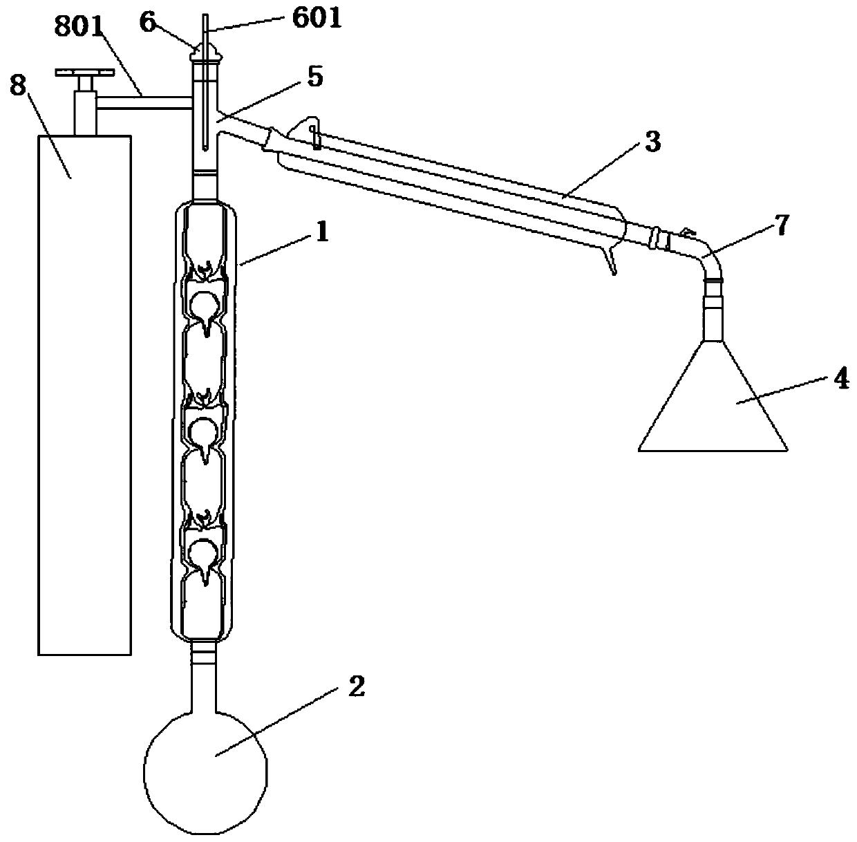
[0027] Embodiment 3: as image 3 As shown, the fractionation device comprises a retort 2, a vacuum interlayer fractionation column 1, a condensation pipe 3 and a receiver 4, the upper end of the retort 2 is detachably connected with the vacuum interlayer fractionation column 1, and the vacuum interlayer fractionation column The upper end of 1 is detachably connected with a fractionation head 5, and one end of the outward extension of the fractionation head 5 is detachably connected with a condensation pipe 3, and the lower end of the condensation pipe 3 is detachably connected with a receiver 4; the fractionation head 5 The top end plug has the bottle stopper 6 with thermometer 601, and described thermometer 601 is inserted in the fractionating head 5 through bottle stopper 6; A plurality of thorn-shaped slots 105 and a plurality of spherical glass plugs 106, the bottom end of the inner column 104 extends outwards with an air inlet 102; the top end of the inner column 104 exte...
PUM
 Abstract
Description
Claims
Application Information
 - R&D Engineer
- R&D Manager
- IP Professional
- Industry Leading Data Capabilities
- Powerful AI technology
- Patent DNA Extraction
Browse by: Latest US Patents, China's latest patents, Technical Efficacy Thesaurus, Application Domain, Technology Topic, Popular Technical Reports.
© 2024 PatSnap. All rights reserved.Legal|Privacy policy|Modern Slavery Act Transparency Statement|Sitemap|About US| Contact US: help@patsnap.com


