Leveling mechanism for vehicle-mounted automatic leveling device

A leveling mechanism and automatic leveling technology, applied in the parts of the instrument, non-rotating vibration suppression, instruments, etc., can solve the problems of low efficiency, inconvenient operation and use, etc., to improve smooth transition and stability, prevent stuck effect

Active Publication Date: 2021-03-09
HUBEI SANJIANG AEROSPACE WANFENG TECH DEV
View PDF6 Cites 0 Cited by
  • Summary
  • Abstract
  • Description
  • Claims
  • Application Information

AI Technical Summary

Problems solved by technology

According to the work requirements, it is impossible to use the structural form of a large-scale vehicle-mounted automatic leveling mechanism for installation and fixation. At present, a split structure is commonly used, that is, the instrument is first placed in a packing box or fixed on a shock absorber, and then placed on a manual or automatic leveling mechanism when in use. It is used on the leveling mechanism, so the operation is very inconvenient and inefficient

Method used


Image

  • Leveling mechanism for vehicle-mounted automatic leveling device
  • Leveling mechanism for vehicle-mounted automatic leveling device
  • Leveling mechanism for vehicle-mounted automatic leveling device

Examples


Embodiment 1

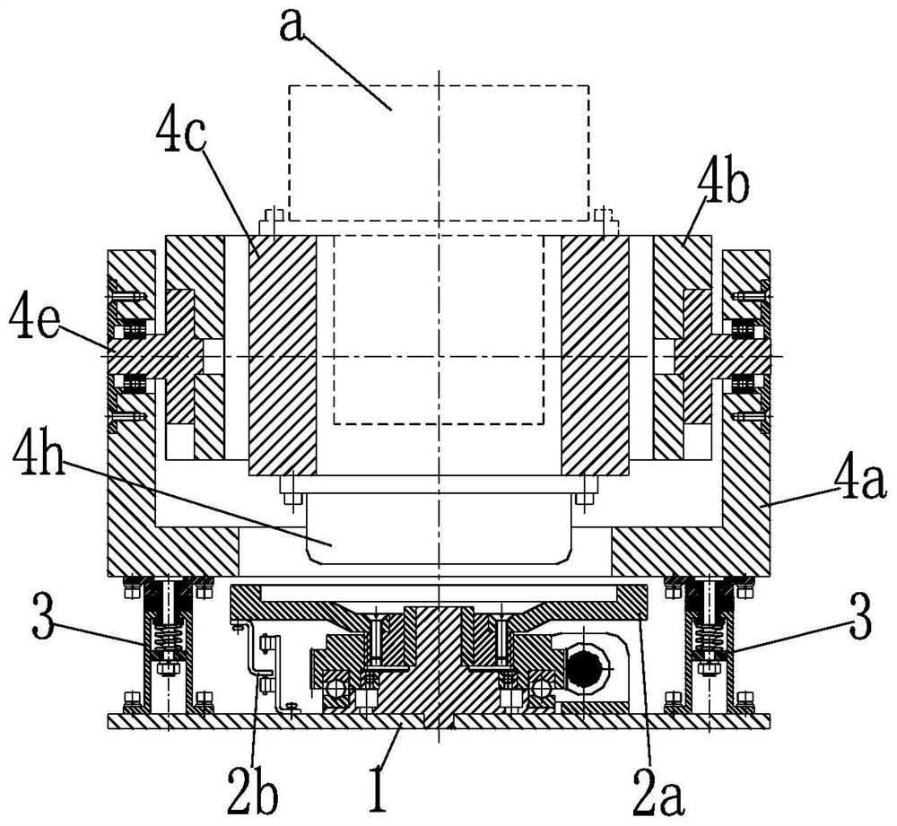
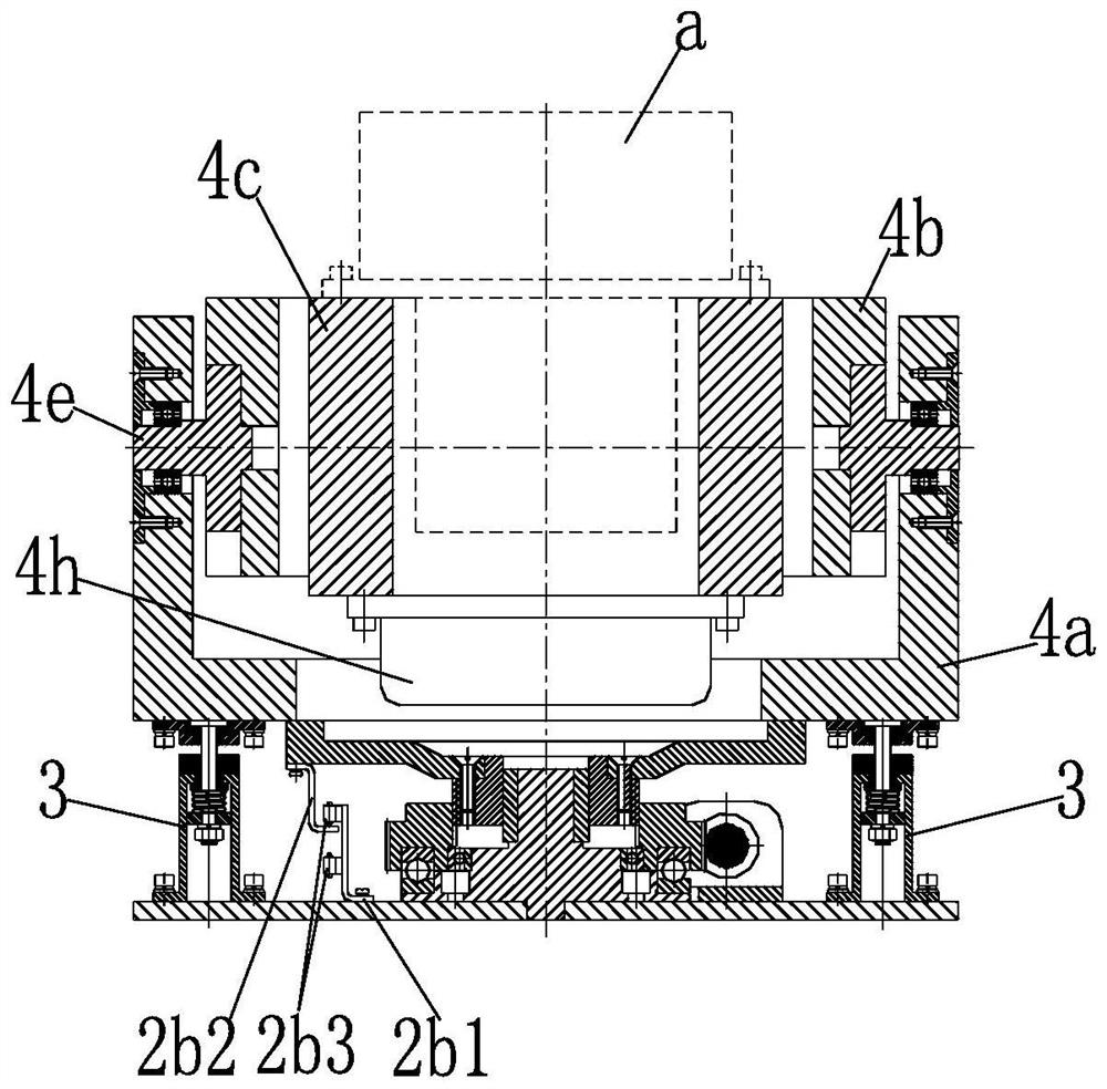
[0089] This embodiment provides a leveling mechanism for a vehicle-mounted automatic leveling device, including an outer frame 4a, a middle frame 4b, and an inner frame 4c, and the top surface of the inner frame 4c is an instrument installation for installing a precision instrument a On the other hand, the two sides of the inner frame 4c are rotatably installed in the middle frame 4b through an inner frame rotating shaft 4d respectively, and the two sides of the middle frame 4b are respectively rotatably installed through a middle frame rotating shaft 4e In the outer frame 4a, the rotation direction of the inner frame 4c is arranged perpendicular to the rotation direction of the middle frame 4b, and there is a set between the outer frame 4a and the middle frame 4b for adjusting the middle frame 4b. A middle frame leveling component 4f for levelness, an inner frame leveling component 4g for adjusting the levelness of the inner frame 4c is provided between the middle frame 4b and...

Embodiment 2

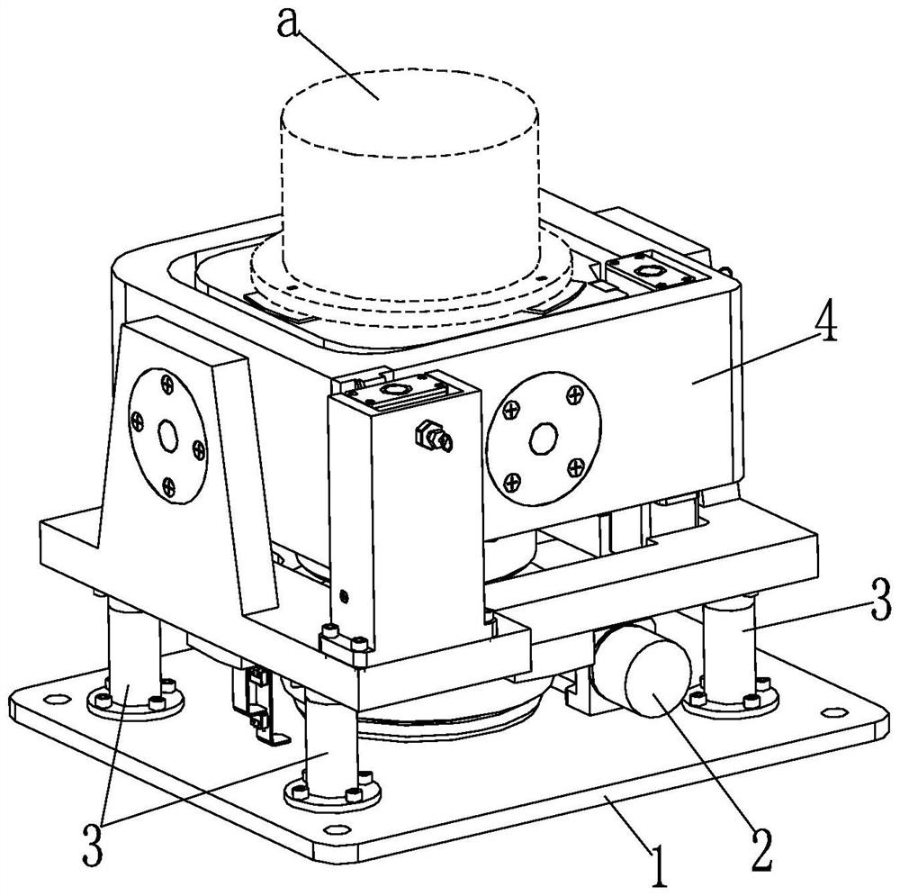
[0109] This embodiment provides a vehicle-mounted automatic leveling device, including a base 1 and a jacking mechanism 2 installed on the base 1, a leveling mechanism 4 is installed on the base 1 through a shock absorbing mechanism 3, and the leveling mechanism 4 is installed on the base 1. The leveling mechanism 4 is located above the jacking mechanism 2. When the jacking plate 2a of the jacking mechanism 2 is at the lowest position, the jacking plate 2a is spaced apart from the bottom surface of the leveling mechanism 4. When the lifting plate 2a of the mechanism 2 is at the highest position, the lifting plate 2a is against the bottom surface of the leveling mechanism 4 . When the leveling device is in use, the precision instrument a is installed on the leveling mechanism 4. When the leveling device is in the shock-absorbing state, the jacking plate 2a of the jacking mechanism 2 is arranged at intervals from the bottom surface of the leveling mechanism 4. , the damping mech...


PUM


Abstract

The invention discloses a leveling mechanism for a vehicle-mounted automatic leveling device. The leveling mechanism includes an outer frame, a middle frame, and an inner frame, the top surface of theinner frame is the instrument mounting surface for mounting a precise instrument, the two sides of the inner frame are rotatably mounted in the middle frame through inner frame rotating shafts respectively, the two sides of the middle frame are rotatably mounted in the outer frame through middle frame rotating shafts respectively, the rotating direction of the inner frame is arranged in particular to the rotating direction of the middle frame, a middle frame leveling assembly for adjusting the level degree of the middle frame is arranged between the outer frame and the middle frame, and an inner frame leveling assembly for adjusting the level degree of the inner frame is arranged between the middle frame and the inner frame. The leveling mechanism is suitable for the vehicle-mounted automatic leveling device.

Description

technical field [0001] The invention relates to the mechanical field, in particular to a leveling mechanism for a vehicle-mounted automatic leveling device. Background technique [0002] At present, many precision instruments need to be used on the leveled workbench after leveling, and these leveling workbenches are divided into two methods: manual leveling and automatic leveling. Automatic leveling generally uses precision instruments fixed on the automatic leveling mechanism , The automatic leveling control is carried out through the leveling mechanism, and the automatic leveling mechanism has three types: fixed type, movable type and vehicle-mounted type. [0003] Among them, the existing large-scale vehicle-mounted automatic leveling mechanisms, such as vehicle-mounted platforms, engineering vehicles, communication vehicles, etc., mostly adopt the principle of multi-point support, and realize automatic leveling of the platform or vehicle by adjusting each hydraulic outri...

Claims


Application Information

Patent Timeline
Patent Type & Authority Patents(China)
IPC IPC(8): G12B5/00F16F15/04
CPCF16F15/04G12B5/00
Inventor 李海峰温传义龙登坛何云峰张惠李兰春
Owner HUBEI SANJIANG AEROSPACE WANFENG TECH DEV
Why Eureka
Try Eureka