
Pure shear test loading device for boards

A loading device, pure shearing technology, applied in the measurement device, using a stable shear force to test the strength of the material, analyzing the material, etc. Guarantee and other issues to achieve the effect of preventing wrinkling and instability

Active Publication Date: 2019-07-19
王渡初
View PDF16 Cites 2 Cited by
  • Summary
  • Abstract
  • Description
  • Claims
  • Application Information

AI Technical Summary

Problems solved by technology

With the progress of shear deformation, there will be additional tensile stress phenomenon in the deformation area, and the degree of influence of tensile stress cannot be described quantitatively, which not only affects the determination of the shear stress value, but also involves the determination of the shear strain value. Accurate determination, that is, it is impossible to guarantee that the material in this area is always in a state of pure shear stress during the whole loading process, which is a problem coexisting with the existing plate shear test methods

Method used


Image

  • Pure shear test loading device for boards
  • Pure shear test loading device for boards
  • Pure shear test loading device for boards

Examples


Embodiment 1

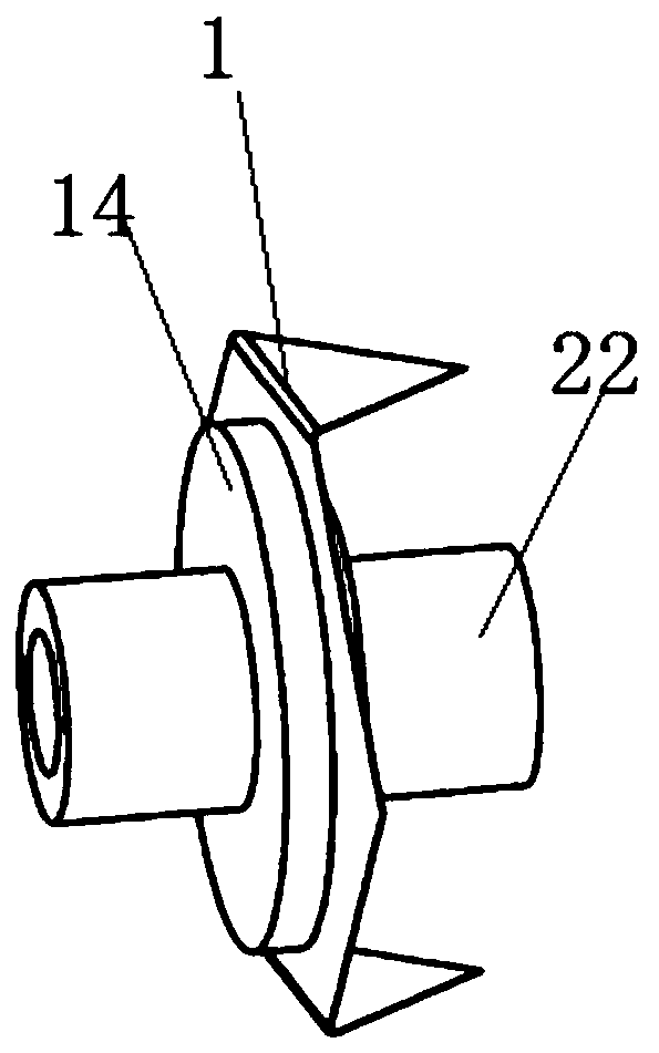
[0026] Example 1: Please refer to Figure 1-5 , a plate pure shear experiment loading device, comprising a plate test piece 1, a front loading device 14 and a rear loading device 22, the plate test piece 1 is arranged between the front loading device 14 and the rear loading device 22, to facilitate the plate test The cutting of piece 1 is convenient for use.

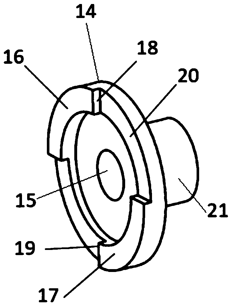
[0027] The front loading device 14 is provided with a front connection torsion testing machine area 21 outside, and the front connection torsion testing machine area 21 is provided with a front loading device positioning hole 15, and the front loading device 14 is provided with a front loading device positioning surface 20, and the front loading device positioning The surface 20 is provided with a front upper shear force application step 16 and a front lower shear force application step 17, and the front upper shear force application step 16 sidewall is a front loading upper shear force application wall 18, and the front...

Embodiment 2

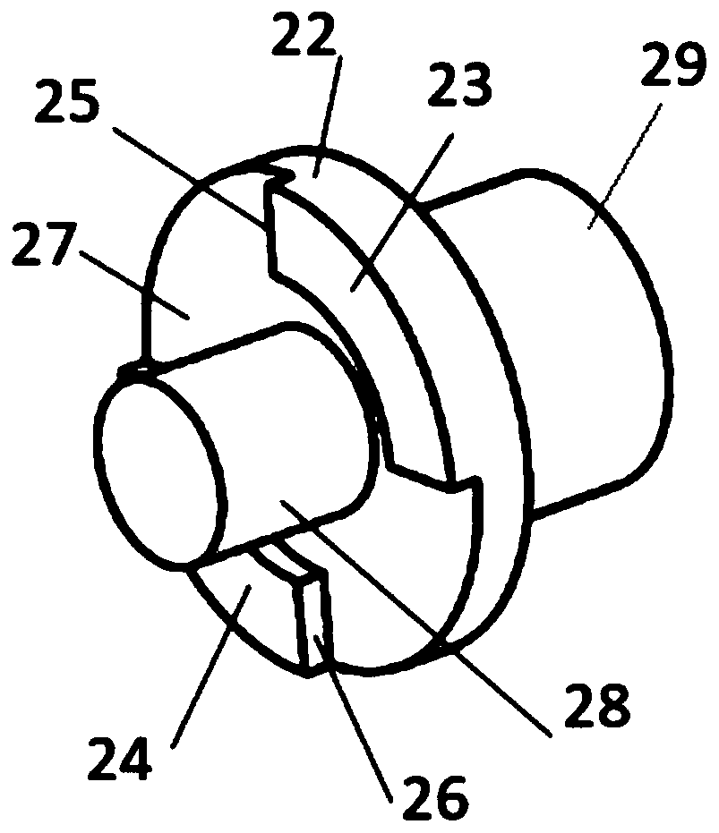
[0034] Embodiment 2: On the basis of Embodiment 1, for the connection of the plate test piece 1 and the rear loading device 22, first, connect the upper inner fan-shaped opening 3 and the lower inner fan-shaped opening 4 of the plate test piece 1 with the rear loading device 22. The upper shear force application step 23 and the rear lower shear force application step 24 are interspersed together, so that the post-load upper shear force application wall 25 and the post-load lower shear force application wall 26 of the post-loading device 22 are connected to the plate specimen 1. The upper inner fan-shaped shear loading wall 5 and the lower inner fan-shaped shear loading wall 6 are close together, and at the same time, the inner surface 13 of the plate test piece 1 and the positioning surface 27 of the rear loading device 22 are close together without gaps, and the plate test piece The outer diameter dimensions of the inner fan-shaped openings 3 and 4 of the piece 1 are the same ...


PUM


Abstract

The invention discloses a pure shear test loading device for boards, and belongs to the technical field of board mechanics performance testing. The device comprises a board test-piece, a front loadingdevice and a rear loading device; the board test-piece is arranged between the front loading device and the rear loading device; a front loading device locating hole is formed in a front connection torsion testing machine area; a front upper shear force applying step and a front lower shear force applying step are arranged on the locating plane of the front loading device; a rear upper shear force applying step and a rear lower shear force applying step are arranged on the locating plane of the rear loading device; and a loading device locating pin is arranged at the center position in the front loading device locating hole. According to the device provided by the invention, via the special relative positions set by the front and rear loading devices, the accurate conversion relation between the shear stress and the load torque can be acquired, and thus the accurate board pure shear test stress-strain relation can be acquired. According to the loading mode, the board can be completelysheared under the pure shear condition.

Description

technical field [0001] The invention relates to the technical field of plate mechanical performance testing, in particular to a plate pure shear test loading device. Background technique [0002] Plates, especially rolled plates, are widely used in national economic production, especially in automobile, aircraft and shipbuilding industries. Products with different geometric shapes are finally formed by different processing techniques, for example, the most commonly used stamping forming process. [0003] In order to avoid failure phenomena such as wrinkling and cracking during the plastic processing of the sheet, it is necessary to understand the mechanical properties of the sheet used, especially with the help of computer numerical simulation technology, to simulate the formability of the sheet during the forming process, including the formation of the sheet Limit prediction, and then rational design and optimization of forming process parameters, can effectively shorten t...

Claims


Application Information

Patent Timeline
IPC IPC(8): G01N3/02G01N3/24
CPCG01N3/02G01N3/24G01N2203/0025
Inventor 胡卫龙王渡初
Owner 王渡初
Learn More