
High-viscosity fluid-oriented reusable liquid level detection head

A liquid level detection, high viscosity technology, applied in the direction of displaying the liquid level indicator through pressure measurement, etc., can solve the problems of difficult liquid level detection of high viscosity fluids and the inability to use the high viscosity fluid liquid level detection device repeatedly, so as to improve the accuracy Effects of Sex and Safety

Active Publication Date: 2019-07-19
CHINA PETROLEUM & CHEM CORP +1
View PDF9 Cites 0 Cited by
  • Summary
  • Abstract
  • Description
  • Claims
  • Application Information

AI Technical Summary

Problems solved by technology

[0004] In order to solve the problem of difficulty in detecting the liquid level of high-viscosity fluid in the prior art, the present invention provides a new reusable liquid-level detection head for high-viscosity fluid
The invention introduces the heating medium such as steam in the crane tube heating jacket into the high and low level liquid level detection device, which not only solves the problem of high viscosity fluid liquid level detection, but also solves the problem that the high viscosity fluid liquid level detection device cannot be used repeatedly

Method used


Image

  • High-viscosity fluid-oriented reusable liquid level detection head
  • High-viscosity fluid-oriented reusable liquid level detection head
  • High-viscosity fluid-oriented reusable liquid level detection head

Examples


specific Embodiment approach I

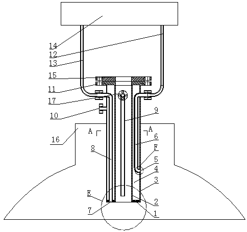
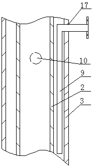
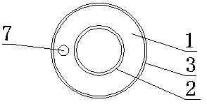
[0029] Specific implementation mode I: as figure 1 -6, the interlayer vertical pipe includes an annular head 1, an inner sleeve 2, an outer sleeve 3, an interlayer vertical pipe flange 11, a heat source inlet 10, a heat source outlet 17, and a heat source outlet pipe 9; wherein, the inner sleeve 2 Coaxially arranged in the outer casing 3; one end of the inner casing 2 and the outer casing 3 is arranged on the interlayer vertical pipe flange 11 at the same time; the other end of the inner casing 2 and the outer casing 3 is sealed by the ring head 1 so that the inner The casing 2, the outer casing 3, the annular head 1 and the interlayer vertical pipe flange 11 together form a closed annular space; wherein, the heat source inlet 10 and the heat source outlet 17 are all arranged on the side wall of the outer casing 3; the heat source outlet 17 The heat source inlet 10 is arranged closer to the interlayer vertical pipe flange 11 and the angle between the heat source outlet 17 and ...

specific Embodiment II

[0034] Specific embodiment II: Both the trachea A6 and the trachea B8 in the above specific embodiment I may be in contact with high-viscosity fluid, which increases the probability of blockage, and can be improved on the basis of specific embodiment I.

[0035] Such as Figure 7-10, the sandwich vertical pipe includes an annular head 1, an inner casing 2, an outer casing 3, a sandwich vertical pipe flange 11, a heat source inlet 10, a heat source outlet 17, and a heat source outlet pipe 9; wherein, the inner casing 2 Coaxially arranged in the outer casing 3; one end of the inner casing 2 and the outer casing 3 is arranged on the interlayer vertical pipe flange 11 at the same time; the other end of the inner casing 2 and the outer casing 3 is sealed by the ring head 1 so that the inner The casing 2, the outer casing 3, the annular head 1 and the interlayer vertical pipe flange 11 together form a closed annular space; wherein, the heat source inlet 10 and the heat source outlet...


PUM


Abstract

In order to solve the problem that the liquid level detection of high-viscosity fluids is difficult in the prior art, the invention provides a high-viscosity fluid-oriented reusable liquid level detection head. The high-viscosity fluid-oriented reusable liquid level detection head comprises an interlayer vertical pipe, a detection assembly arranged in the interlayer vertical pipe, and a pneumatic-electric converter connected with the output ends of detection pipes, wherein the interlayer vertical pipe comprises an inner sleeve and an outer sleeve coaxial with the inner sleeve; an airtight space is formed between the inner sleeve and the outer sleeve; the outer sleeve is connected with a heat supply device to ensure that a thermal medium output by the heat supply device is communicated witha space formed between the inner sleeve and the outer sleeve; the detection assembly comprises two detection pipes which are arranged between the inner sleeve and the outer sleeve; and the two detection pipes and the outer sleeve form a high detection port and a low detection port. During the measurement, the high-viscosity fluids entering the detection pipes are continuously heated so that the high-viscosity fluids cannot be attached to the inner side walls of the detection pipes, thereby realizing repeated using.

Description

technical field [0001] The invention relates to the field of petrochemical tank truck loading, in particular to a reusable liquid level detection head for liquid level detection for high-viscosity fluids. Background technique [0002] At present, in the field of high-viscosity liquid level detection such as crude oil, asphalt, and liquid sulfur in the modern petrochemical industry, especially when tankers are filled with high-viscosity fluids such as crude oil, asphalt, and liquid sulfur, it is still impossible to achieve due to the conditions of the loading site. Automatic detection, during the loading process, the switch of the valve is controlled by manual visual inspection of the liquid level. [0003] At the same time, due to the characteristics of the above-mentioned high-viscosity fluid, after a general liquid level detection device is used once, it will be adhered by the high-viscosity fluid and cannot be used again, resulting in high cost. Contents of the inventio...

Claims


Application Information

Patent Timeline
Patent Type & Authority Applications(China)
IPC IPC(8): G01F23/14G01F23/18
CPCG01F23/14G01F23/18
Inventor 翟志清李晓昌耿庆光孙宁飞李创裴丽丽侯玉宝李清松李中新郭明中宋世波秦继伟由召举吴彦林梁心合张长轩
Owner CHINA PETROLEUM & CHEM CORP
Learn More