Device for ensuring stamping symmetry of annular supporting ring U-shaped semi-finished product of illuminating lamp of dental operating chair

The technology of operating chair and semi-finished product is applied in the field of punching symmetry guarantee device for U-shaped semi-finished product of annular support ring of dental operating chair lighting, which can solve the problem of different heights of side uprights, difficulty in pressing into a ring shape, and different height differences. OK, etc.

Inactive Publication Date: 2019-07-19
杜宗英
View PDF10 Cites 0 Cited by
  • Summary
  • Abstract
  • Description
  • Claims
  • Application Information

AI Technical Summary

Problems solved by technology

[0004] However, in the above working process, there will be relative frictional movement between the rectangular steel plate and the two rounded edges, and the speed and distance of the relative movement of the two positions are not necessarily equal, which will eventually cause the two side uprights to be of different heights , the height difference is large or small, and it is difficult for the next process to press into a circular ring

Method used


Image

  • Device for ensuring stamping symmetry of annular supporting ring U-shaped semi-finished product of illuminating lamp of dental operating chair
  • Device for ensuring stamping symmetry of annular supporting ring U-shaped semi-finished product of illuminating lamp of dental operating chair
  • Device for ensuring stamping symmetry of annular supporting ring U-shaped semi-finished product of illuminating lamp of dental operating chair

Examples


Embodiment

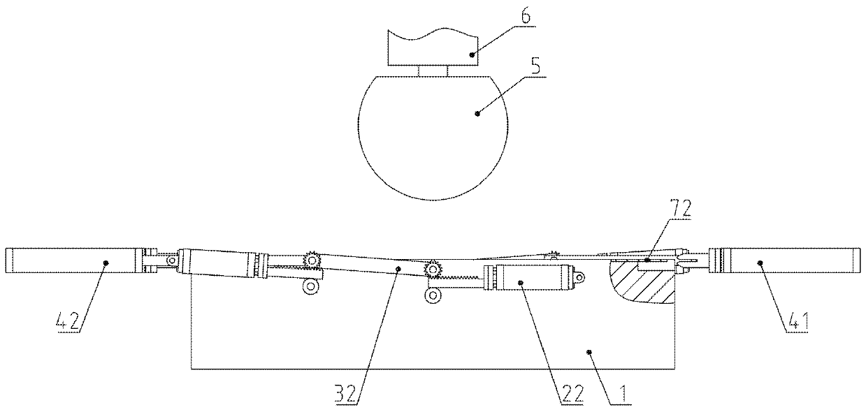
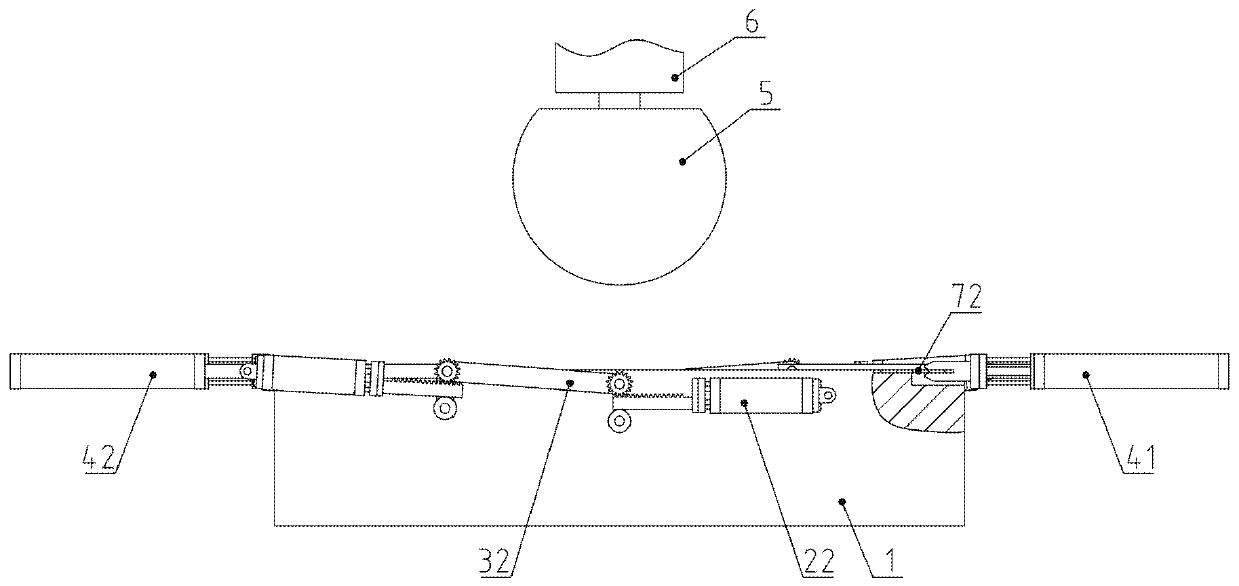
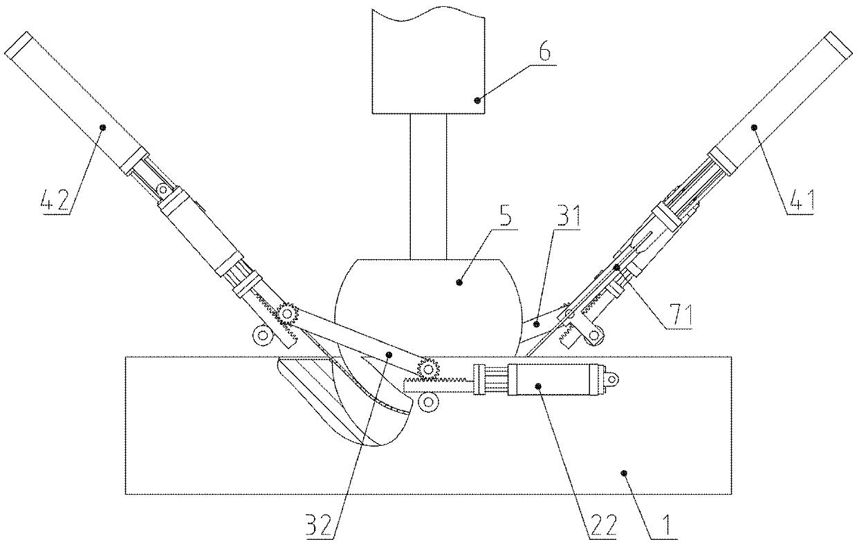
[0069] Example: see Figure 1 to Figure 21 .

[0070] A device for guaranteeing the symmetry of a U-shaped semi-finished product stamping of a dental operating chair illumination lamp ring, including a lower mold assembly 1 and an upper mold 5, the lower mold assembly 1 includes a lower mold base 11, and the lower mold base 11 has an upper positioning groove 111, the depth of upper positioning groove 111 is equal to the thickness of rectangular steel plate 72, and the length and width of upper positioning groove 111 are equal to the length and width of rectangular steel plate 72 respectively, and the middle part of upper positioning groove 111 is provided with semicircle groove 112, semicircle groove 112 The radius equals the outer radius of the semicircular portion at the bottom of the U-shaped semi-finished product, and the upper positioning groove 111 and the semicircular groove 112 are adjacent to the rounded corrugated edge 115; the upper mold 5 is semicircular, and the s...


PUM


Abstract

The invention belongs to the technical field of medical equipment manufacturing, and relates to a device for ensuring stamping symmetry of an annular supporting ring U-shaped semi-finished product ofan illuminating lamp of a dental operating chair. Through three flow distributing and collecting valves, the moving position of the combination of a first horizontal hydraulic cylinder assembly, a first swing arm assembly and a first pressing assembly can be bilaterally symmetrical to the moving position of the combination of a second horizontal hydraulic cylinder assembly, a second swing arm assembly and a second pressing assembly; when an upper die is to press on a rectangular steel plate, two H-shaped middle position three-position four-way electromagnetic valves are changed to the middle position, and the first horizontal hydraulic cylinder, the second horizontal hydraulic cylinder, a first swinging hydraulic cylinder and a second swinging hydraulic cylinder are in a floating state atthe same time; and the upper die continues to punch, the center of the rectangular steel plate is pressed and concaved, the two sides of the rectangular steel plate respectively slide relative to theedge of a rounding, and the two ends of the rectangular steel plate are warped upwards, so that the formed U-shaped semi-finished product is in a completely bilaterally symmetrical U shape. Accordingto the device, the rectangular steel plate is corrected in the manufacturing process of the U-shaped semi-finished product, so that the equal height of two side vertical parts is ensured, the yield isimproved, and the manufacturing cost of the products is reduced.

Description

technical field [0001] The invention belongs to the technical field of medical equipment manufacturing, and relates to a manufacturing equipment for components of a dental operating chair, in particular to a stamping symmetry guarantee device for a U-shaped semi-finished product of an annular support ring of a dental operating chair lighting lamp. Background technique [0002] There is a ring-shaped support ring inside the lamp holder of the light equipped on the dental surgery chair. The most traditional production method is to circle it manually to form a ring. The production efficiency is low, the roundness tolerance is relatively low, and the quality of the product is not good. With the development of automated industrial production, it is now possible to make a set of automated production equipment to press it into shape. For example, in the first process, the raw material rectangular steel plate is pressed into a U-shaped semi-finished product. The U-shaped semi-finish...

Claims


Application Information

Patent Timeline
IPC IPC(8): B21D5/02B21D43/00B21D53/16
CPCB21D5/002B21D5/0209B21D5/0245B21D53/16
Inventor 不公告发明人
Owner 杜宗英
Why Eureka
Try Eureka