
Variable impedance circuit

A technology of circuit and coupling circuit, applied in the direction of impedance network, single resonant circuit with only variable inductance/capacitance, system using coupling circuit, etc., can solve problems such as bulky and expensive PLC circuits

Active Publication Date: 2019-07-16
SOLAREDGE TECH LTD
View PDF4 Cites 4 Cited by
  • Summary
  • Abstract
  • Description
  • Claims
  • Application Information

AI Technical Summary

Problems solved by technology

PLC circuits that are effective in the frequency range (eg tens of kilohertz) can be expensive and / or bulky

Method used


Image

  • Variable impedance circuit
  • Variable impedance circuit
  • Variable impedance circuit

Examples


Embodiment Construction

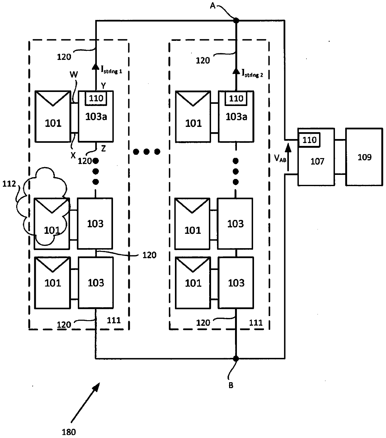
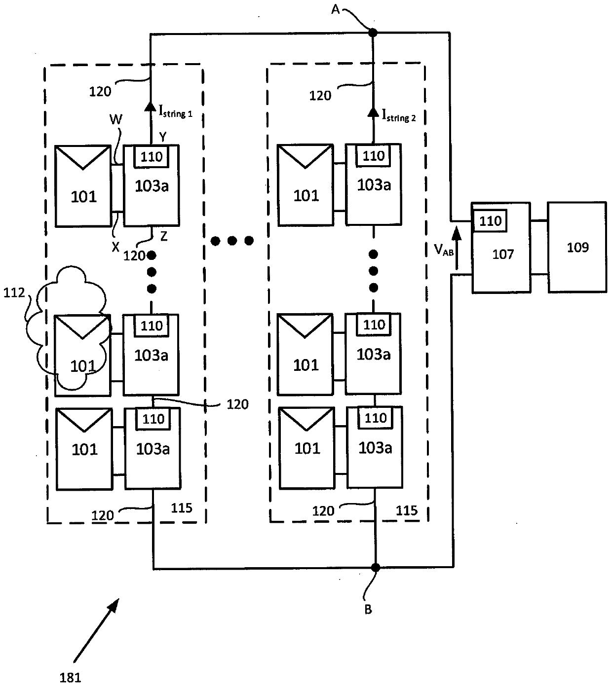
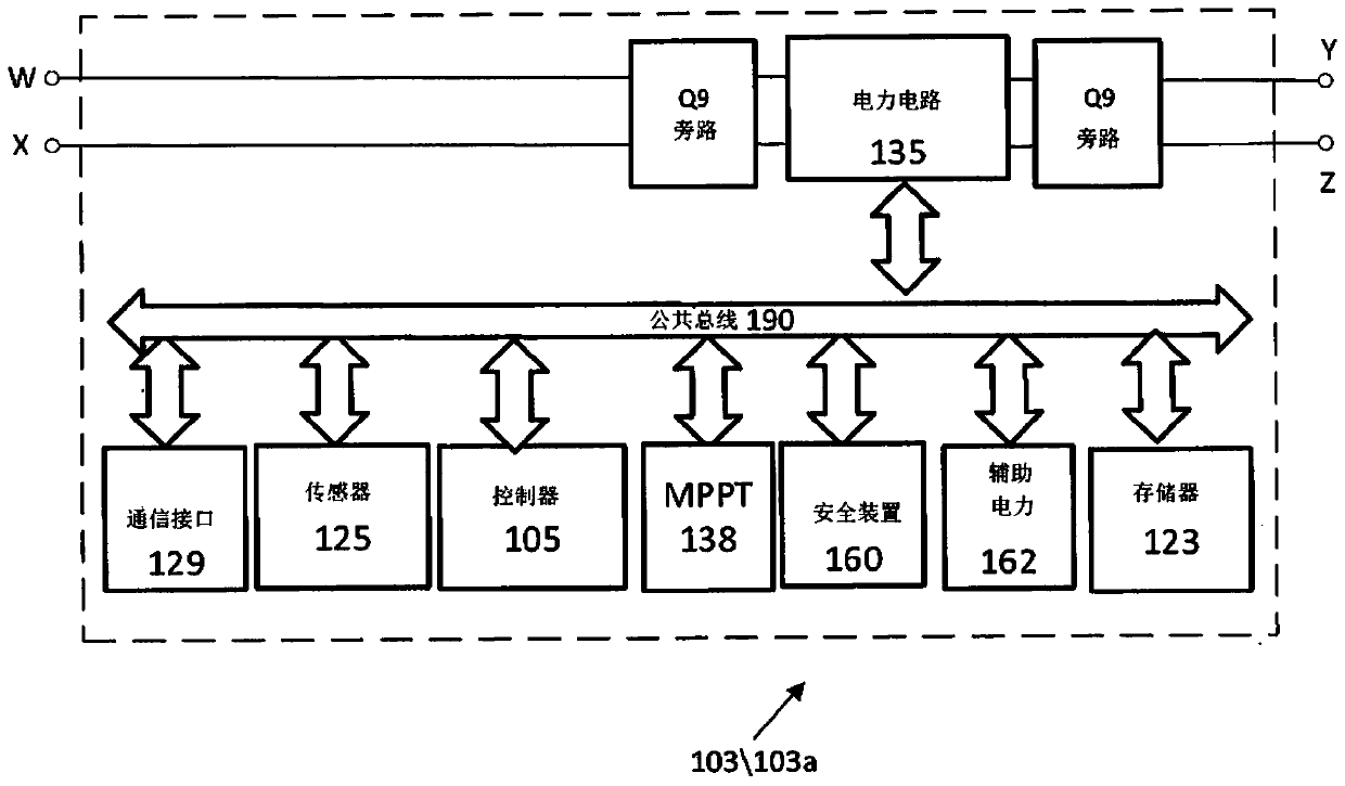
[0029] In the following description of various exemplary aspects of the present disclosure, reference is made to the accompanying drawings (which form a part of this disclosure), in which are shown illustratively various aspects of the present disclosure that can be realized by the aspects of the present disclosure. Program. It is to be understood that other aspects of the present disclosure may be utilized and structural and functional modifications may be made without departing from the scope of the present disclosure.

[0030] In the detailed description, the expression "multiple" as used herein refers to the property of having or comprising several parts, elements or members. In the claims section, the expression "plurality" of the claims as used herein is supported in the description using the expression "plurality" and / or other plural forms. Other plural forms may include, for example, regular nouns that are pluralized by adding the letters s or es, eg such that a plura...


PUM


Abstract

A power line communication device including a current path provided between a first terminal and a second terminal. A coupling circuit includes a first circuit of a first inductor connected in parallel with a first capacitor and a first resistor, wherein the coupling circuit is connected between the first and second terminals. A sensor is configured to sense a communication parameter of the coupling circuit. The communication parameter may be a resonance of the first circuit, the quality (Q) factor of the resonance, the bandwidth (BW) of the coupling circuit, the resistance of the first resistor, or the impedance of the first circuit. A transceiver is adapted to couple to the first and second terminal to transmit a signal onto the current path or receive a signal from the current path responsive to the parameter of the coupling circuit and a level of current in the current path sensed by the sensor.

Description

[0001] Cross References to Related Applications [0002] This application claims priority to US Provisional Application Serial No. 62 / 611,006, filed December 28, 2017, entitled "Variable Impedance Circuits," the entire contents of which are incorporated herein by reference. Background technique [0003] Inductor design usually involves selecting the desired inductance (L) and the desired saturation current (I sat ), that is, the current at which the inductor ceases to operate as an effective inductor. Typically, there is a tradeoff between achieving high inductance and achieving high saturation current. Inductors that have both high inductance and high saturation current are often expensive and / or physically large and bulky. It would be desirable to have a circuit operable to function similarly to an inductor with high inductance and high saturation current, at a fraction of the cost and volume of a passive inductor with the same performance. [0004] Power line communicati...

Claims


Application Information

Patent Timeline
Patent Type & Authority Applications(China)
IPC IPC(8): H04B3/54H04B3/56H03H7/38
CPCH04B3/54H04B3/56H03H7/38H04B2203/5483H03J3/20H03J3/24H04B1/04H04B1/16H04B2203/5404H04B2203/5429H04L25/0264
Inventor 奥菲尔·比伯
Owner SOLAREDGE TECH LTD
Learn More