A Direction Finding Method Combining Sum-difference Beam and Beam Music
A differential beam and combined technology, applied in the field of antennas, can solve problems such as ambiguity of angle, impossibility of application, and high computational complexity
- Summary
- Abstract
- Description
- Claims
- Application Information
AI Technical Summary
Problems solved by technology
Method used
Image
Examples
Embodiment 1
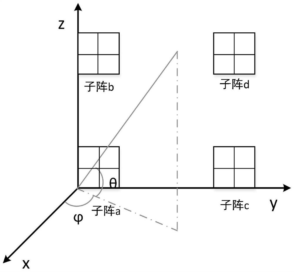
[0077] In this example, if figure 1 as shown, figure 1 is the distribution model of the distributed array; four rectangular sub-arrays with the number of array elements of 32×32 are respectively distributed at the vertices of a square field to form a distributed array, and the rectangular sub-arrays are figure 1 For sub-array a, sub-array b, sub-array c, and sub-array d, the side length of the site is set to 500 times the signal wavelength. Construct the first coordinate system according to the distributed array, such as figure 1 As shown, the array elements are all distributed on the yoz plane, and the coordinates are (y n ,z n ), wherein n=1, 2, ... M, M is the number of array elements in the distributed array. The angle between the projection of the incident signal on the xoy plane and the x-axis is the azimuth angle, which is denoted as The included angle between the incident signal and the projection is the elevation angle, denoted as θ. It is worth pointing out th...
Embodiment 2
[0109] Specifically, the step S1 includes: the beam pointing scanning of the step S11 adopts the Bartlett algorithm, and the Bartlett algorithm is to point the main beam of the distributed array to a certain direction, and the received information of each array element on the distributed array The signals are weighted and summed. When the sum signal power is maximum, the direction of the main beam at this time is close to the direction of the signal.
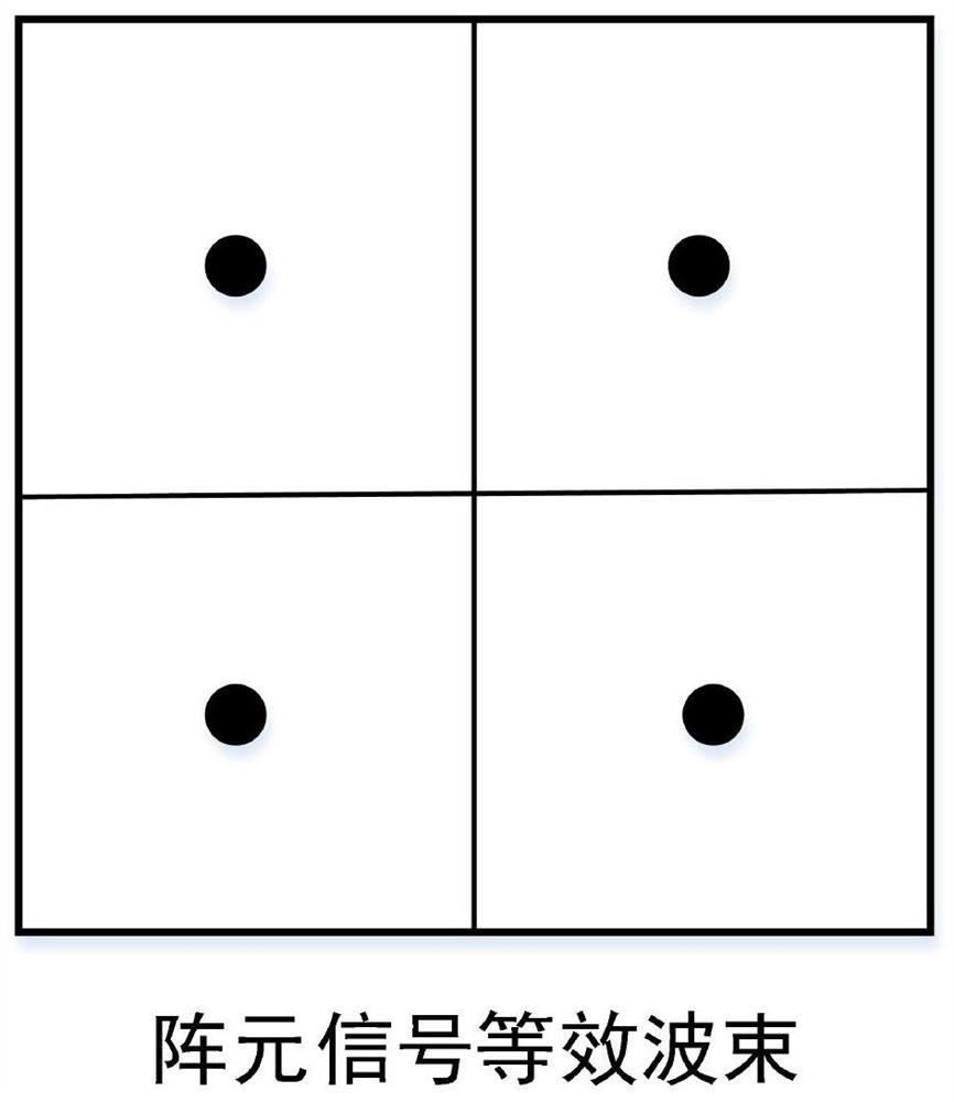
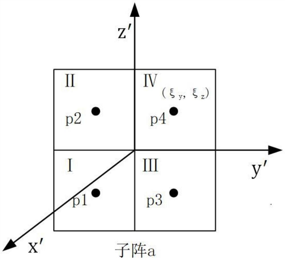
[0110] Specifically, according to image 3 As shown, a certain sub-array in the distributed array is divided into four planar arrays with up-down and left-right symmetry, which are denoted as planar array I, planar array II, planar array III, and planar array IV. The y' axis and the z' axis take the intersection point O of the dividing line as the origin to construct the second coordinate system, and the center p of each described surface array 1 ,p 2 ,p 3 ,p 4 In the second coordinate system, the origin is symmetrical, and ...
Embodiment 3
[0142] In a specific embodiment, four 32×32 rectangular sub-arrays are distributed at the vertices of the rectangular field (only for simulation, the actual sub-arrays can be irregularly distributed in any position in the field), and the target signal is a narrowband BPSK signal, carrying When the frequency is 2.2GHz and the signal-to-noise ratio of the signal channel of a single array element is -31db, the relationship between the final direction-finding accuracy and the side length of the site is as follows Figure 4 .
[0143] It can be seen that in the range of 800 times the wavelength (about 100 meters), the above direction finding methods can all obtain higher direction finding accuracy.
[0144] When the size of the fixed site is 800 times the wavelength, and the signal-to-noise ratio of the array element channel is changed, the simulation results are as follows Figure 5 , it can be seen that when the signal-to-noise ratio of a single array element channel is not lowe...
PUM
 Abstract
Description
Claims
Application Information
 - R&D
- Intellectual Property
- Life Sciences
- Materials
- Tech Scout
- Unparalleled Data Quality
- Higher Quality Content
- 60% Fewer Hallucinations
Browse by: Latest US Patents, China's latest patents, Technical Efficacy Thesaurus, Application Domain, Technology Topic, Popular Technical Reports.
© 2025 PatSnap. All rights reserved.Legal|Privacy policy|Modern Slavery Act Transparency Statement|Sitemap|About US| Contact US: help@patsnap.com


