
Workroom and clean room system

A technology of working space and clean space, which is applied in the field of clean space system, and can solve problems such as the impact of use cost and high-cost cleaning work

Active Publication Date: 2019-07-16
FESTO AG & CO KG
View PDF5 Cites 0 Cited by
  • Summary
  • Abstract
  • Description
  • Claims
  • Application Information

AI Technical Summary

Problems solved by technology

Therefore, in order to permanently maintain the desired cleanliness requirements for the corresponding workspace, complex cleaning tasks must be carried out
These cleaning tasks are especially carried out manually by the operator using cleaning agents such as liquid cleaners (Putzmitteln) and cleaning cloths, whereby in addition to a large amount of work costs an additional amount of waste occurs, so that the necessary Cleaning has a negative impact on the cost of using the workspace

Method used


Image

  • Workroom and clean room system
  • Workroom and clean room system
  • Workroom and clean room system

Examples


Embodiment Construction

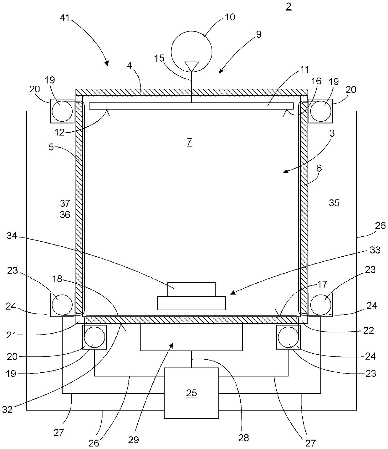
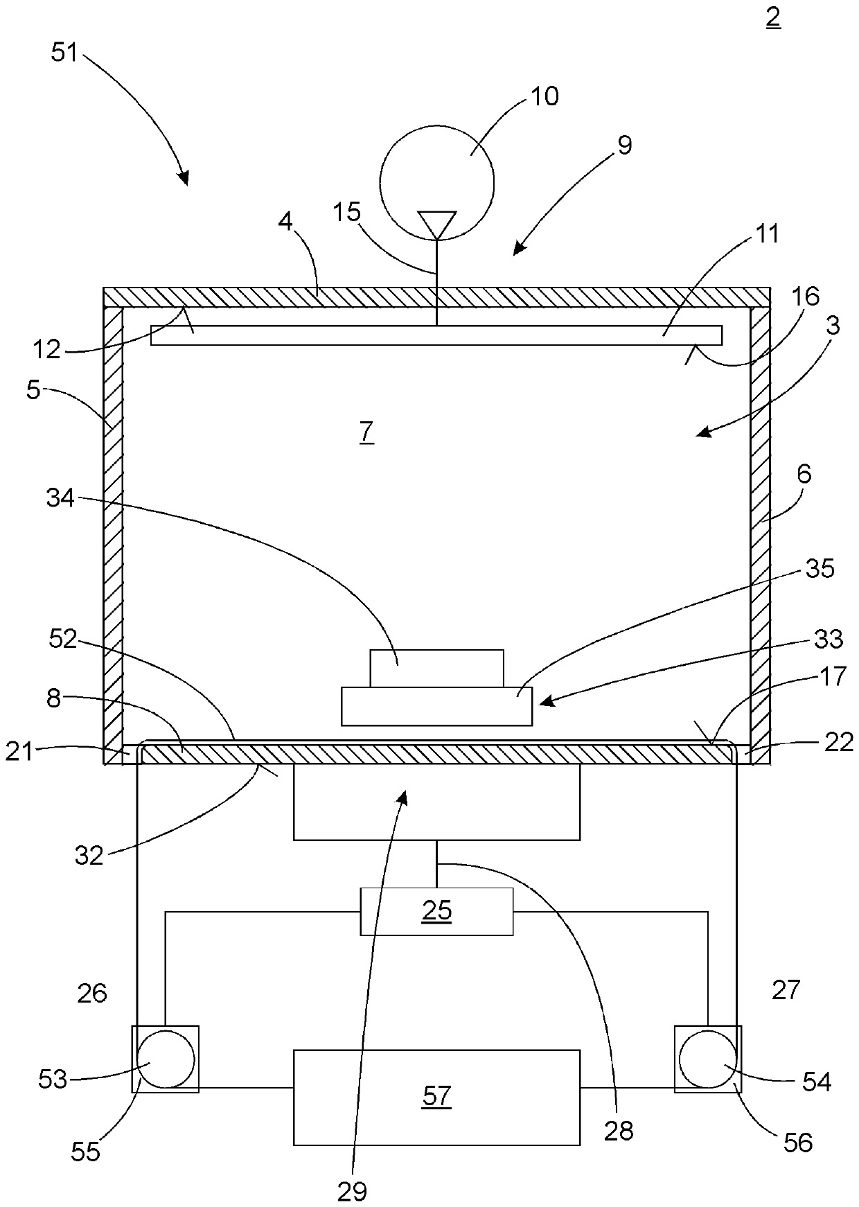
[0032] figure 1 The workspace 1 shown in is provided to provide a work volume 3 separate from the environment 2 , wherein predeterminable cleanliness conditions are ensured in the work volume 3 , in particular when deviating from the environment 2 . Such a workspace 1 is also referred to as a safety workbench, isolator or clean space box.

[0033] In order to ensure a separation between the working volume 3 and the environment 2 , the working space 1 comprises, purely by way of example, a total of six wall sections 4 , 5 , 6 , 7 , 8 , respectively configured as planar rectangular plates, where the front wall segment is due to figure 1 The sectional illustration of , which is not shown, the front wall section closes the working volume 3 delimited by the wall sections 4 , 5 , 6 , 7 , 8 . Purely by way of example, it is provided that a wall section 4 to 8 is connected to an adjacent wall section 4 to 8 in each case on the edge side, thereby resulting in an at least almost compl...


PUM


Abstract

The invention relates to a work space for carrying out a work operation on a work object (34). The work space comprises a working volume (3; 68) bounded by a plurality of wall sections (4, 5, 6, 7, 8;77) correspondingly connected to each other on edge sides, wherein at least one of the inner surfaces (12, 17; 42, 43,; 74, 75, 76) of the wall sections (4, 5, 6, 7, 8; 77) is covered by a replacement membrane (18; 52; 62).

Description

technical field [0001] The invention relates to a workspace for carrying out work processes on a work object, the workspace having a work volume delimited by a plurality of wall sections which are connected to each other at the edge sides. Furthermore, the invention relates to a clean room system having a plurality of such workspaces. Background technique [0002] In known workspaces, also known as clean space cabinets or safety workbenches, a continuous, in particular laminar, air flow is guided through a working volume delimited by the workspace. For this purpose, corresponding inflow openings for the air flow can be provided, for example, on the side wall sections or on the top wall sections, while in the wall sections serving as bottom or on the side wall sections Outflow openings in the lower region of the segment enable the outflow of the air flow. Due to the flow properties of the air flow, such workspaces always have regions in which a concentration of dirt particl...

Claims


Application Information

Patent Timeline
Patent Type & Authority Applications(China)
IPC IPC(8): B01L1/04B01D46/54B01D53/22B01D65/02
CPCB01L1/04B01D46/543B01D53/22B01D65/02B01D2321/22
Inventor S.绍茨U.普拉赫特F.豪贝尔
Owner FESTO AG & CO KG
Learn More