
Garbage incinerator with circular structure

A waste incinerator and circular technology, which is applied to incinerators, grate, combustion methods, etc., can solve the problems of insufficient combustion of waste, complicated slag discharge devices, and large floor space, so as to achieve simple slag discharge and land occupation. Small area, not easy to agglomerate and burn

Active Publication Date: 2019-07-12
DONGFANG BOILER GROUP OF DONGFANG ELECTRIC CORP
View PDF11 Cites 0 Cited by
  • Summary
  • Abstract
  • Description
  • Claims
  • Application Information

AI Technical Summary

Problems solved by technology

[0003] In view of the problems faced by the current square-arranged garbage incinerator structure, such as large amount of slag leakage, serious wear of grate pieces, insufficient garbage combustion, complicated slag discharge device, and large footprint, the present invention proposes a circular structure with a rotary furnace row of waste incinerators

Method used


Image

  • Garbage incinerator with circular structure
  • Garbage incinerator with circular structure
  • Garbage incinerator with circular structure

Examples


Embodiment Construction

[0018] All features disclosed in this specification, or steps in all methods or processes disclosed, may be combined in any manner, except for mutually exclusive features and / or steps.

[0019] Any feature disclosed in this specification, unless specifically stated, can be replaced by other alternative features that are equivalent or have similar purposes. That is, unless expressly stated otherwise, each feature is one example only of a series of equivalent or similar features.

[0020] The layout structure of the thermal system of the circulating fluidized bed burning ultra-high ash fuel of the present invention will be specifically described and illustrated below.

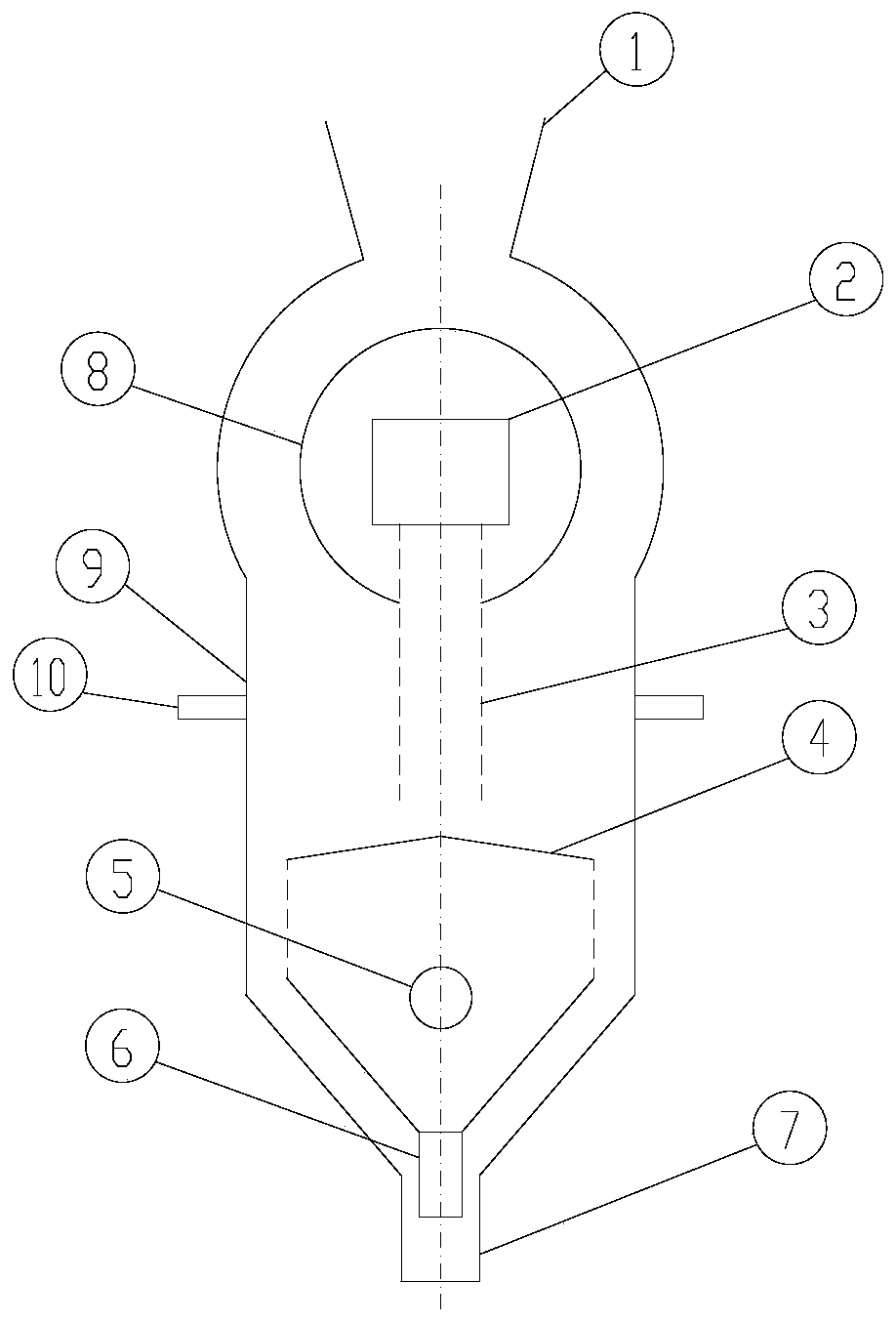
[0021] figure 1 A schematic structural diagram of a circular structure garbage incinerator according to an exemplary embodiment of the present invention is shown.

[0022] like figure 1 As shown, according to an exemplary embodiment of the present invention, the garbage incinerator of the circular structure in...


PUM


Abstract

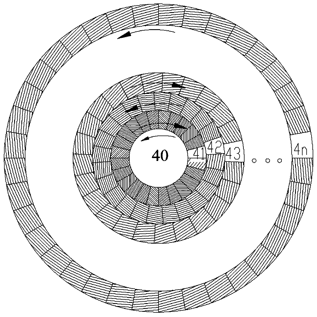
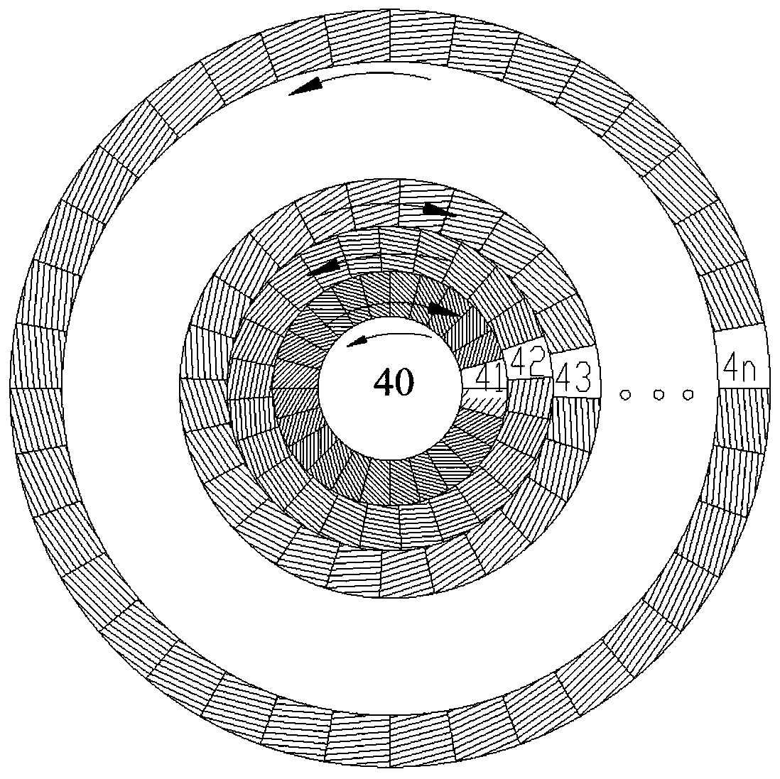
The invention discloses a garbage incinerator with a circular structure. The garbage incinerator with the circular structure comprises an incinerator wall and a circular section hearth formed by the incinerator wall in a surrounding mode; a material falling pipe, a fire grate and a primary air supplying unit are arranged in the hearth; the fire grate comprises a middle material falling disc and aplurality of fire grate rings which are arranged around the material falling disc, and the diameters of the fire grate rings are gradually increased; an outlet of the material falling pipe faces the material falling disc of the fire grate; the primary air supplying unit is arranged under the fire grate; and the material falling disc and the fire grate rings of the fire grate both do circular motion, and every two adjacent assemblies of the fire grate do relative motion. According to the garbage incinerator with the circular structure, the occupation area is smaller compared with a garbage incinerator with a square structure, every two adjacent assemblies of the fire grate do relative motion, therefore, garbage is subjected to more shearing force on the fire grate, and the garbage is not prone to being agglomerated and is combusted more fully; the fire grate does not make contact with the incinerator wall in the whole movement process, and therefore the problem that slag is leaked due to fire grate movement can not occur; the fire grate rings do circular motion, and therefore a driving system is simpler; and few slag discharge outlets are arranged, the positions are single, and therefore slag discharge is easier.

Description

technical field [0001] The invention relates to the technical field of environmental protection for garbage utilization, and more specifically, relates to a garbage incinerator with a circular structure. Background technique [0002] With the progress of urbanization in our country and the continuous improvement of people's living standards, more and more urban wastes are produced, and waste incineration power generation is more and more favored by local governments. At present, waste incineration is usually carried out in waste incinerators, and waste incinerators are usually arranged in a square shape, which faces problems such as large slag leakage, serious wear of grate pieces, insufficient waste combustion, complicated slag discharge devices, and large floor space. Contents of the invention [0003] In view of the problems faced by the current square-arranged garbage incinerator structure, such as large amount of slag leakage, serious wear of grate pieces, insufficien...

Claims


Application Information

Patent Timeline
Patent Type & Authority Applications(China)
IPC IPC(8): F23G5/00F23G5/44F23H9/00F23H15/00F23L1/00F23L9/00
CPCF23G5/002F23G5/442F23H9/00F23H15/00F23L1/00F23L9/00
Inventor 董康翟少栋许钞俊汪小继王诗行苏虎巩李明
Owner DONGFANG BOILER GROUP OF DONGFANG ELECTRIC CORP
Learn More