Heart rate patch and heart rate monitor

A technology of heart rate and heart rate sensor, which is applied in the direction of measuring pulse rate/heart rate, diagnostic recording/measurement, sensor, etc., can solve the problems of arterial semi-compression, poor blood flow, inconvenience, etc., and achieve the effect of improving lightness rate

Pending Publication Date: 2019-07-12
GUANGZHOU SHIYUAN ELECTRONICS CO LTD +1
View PDF0 Cites 1 Cited by
  • Summary
  • Abstract
  • Description
  • Claims
  • Application Information

AI Technical Summary

Problems solved by technology

However, the pressure sensor needs to semi-compress the wearer's artery for a long time, causing discomfort, and it is difficult to fix the pressure sensor on the skin surface in a suitable way. If it is fixed too tightly, it will cause poor blood flow, and if it is too loose, it will not be able to achieve measurement. Inconvenient to use
[0005] In the existing heart rate test, it is necessary to wear various clamp-type instruments, which restricts the activity space of the tester to a certain extent and brings various inconveniences

Method used


Image

  • Heart rate patch and heart rate monitor
  • Heart rate patch and heart rate monitor
  • Heart rate patch and heart rate monitor

Examples


Embodiment 1

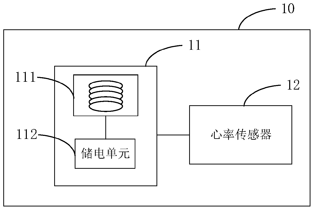
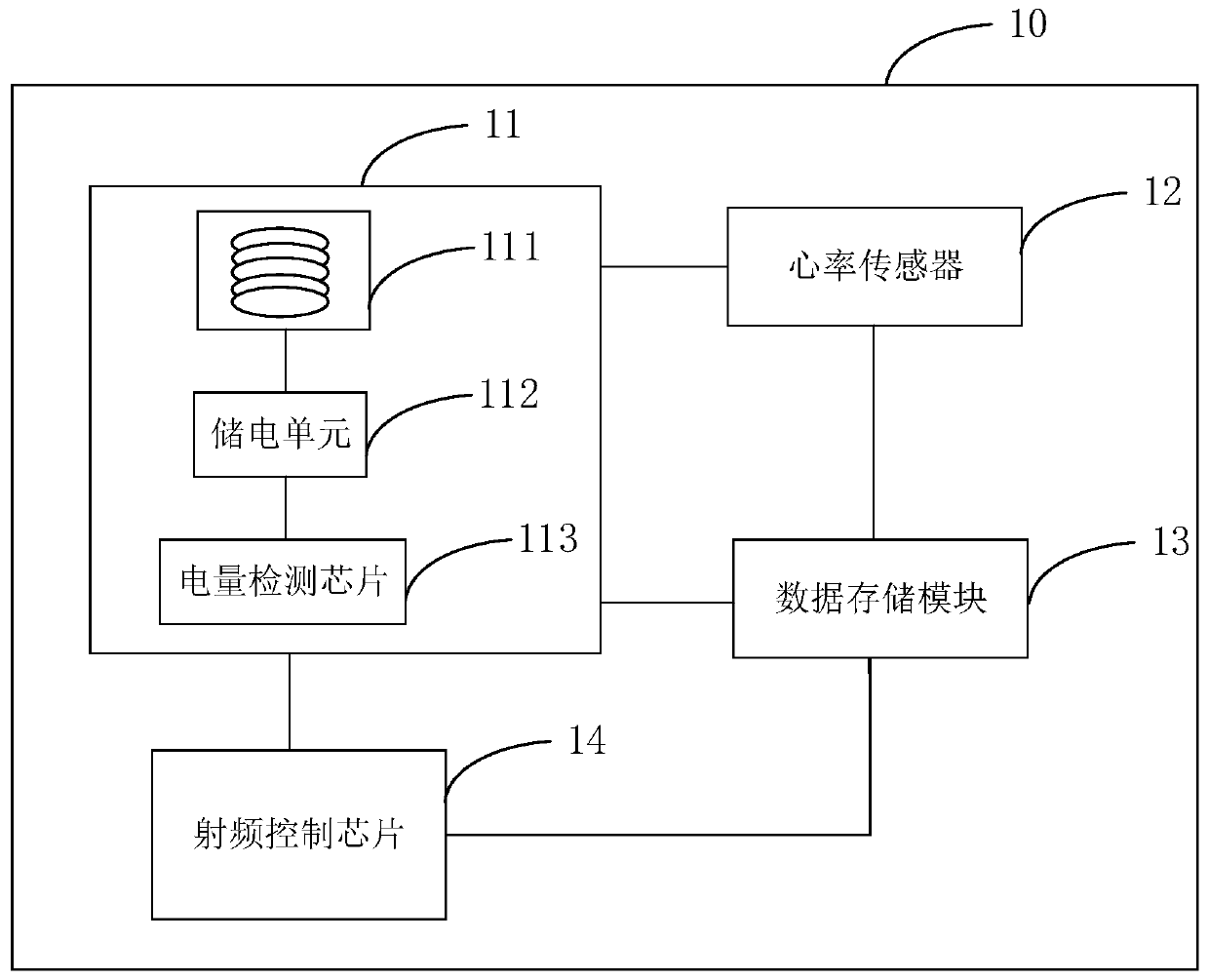
[0029] figure 1 It is a schematic structural diagram of the heart rate patch in Embodiment 1 of the present invention. Such as figure 1 As shown, the heart rate sticker 10 includes: a power supply module 11 and a heart rate sensor 12, wherein the power supply module 11 is connected to the heart rate sensor 12 for supplying power to the heart rate sensor 12; the power supply module 11 includes a coil winding 111 and a power storage unit 112, the coil The winding 111 and the external generating coil generate electric energy through electromagnetic induction and store the electric energy in the power storage unit 112; the heart rate sensor 12 is used to detect the user's heart rate and obtain heart rate detection data.

[0030] The heart rate sticker 10 in this embodiment can take the shape of a post-it note. The external generating coil can be inductively powered by an AC power supply, and an electromagnetic field of a certain frequency is generated when the alternating curren...

Embodiment 2

[0044] Image 6 It is a schematic structural diagram of the heart rate monitor in Embodiment 2 of the present invention. Image 6 A block diagram of an exemplary heart rate monitor 20 is shown. Image 6 The heart rate monitor 20 shown is only an example and should not impose any limitation on the functions and scope of use of the embodiments of the present invention.

[0045] Such as Image 6 As shown, the heart rate monitor 20 may include the heart rate patch 10 , the generating coil 21 and the radio frequency reading chip 22 as described above. Wherein, the generating coil 21 is used to provide alternating current and the coil winding 111 in the heart rate sticker 10 to generate electric energy through electromagnetic induction. The radio frequency reading chip 22 is used to obtain heart rate detection data by identifying the radio frequency control chip 14 in the heart rate sticker 10 .

[0046] Further, the radio frequency reading chip 22 may include a radio frequency ...


PUM


Abstract

The embodiment of the invention discloses a heart rate patch and a heart rate monitor. The heart rate patch comprises a power supply module and a heart rate sensor, and the power supply module is connected with the heart rate sensor and used for supplying power to the heart rate sensor; the power supply module comprises a coil winding and an electricity storage unit, the coil winding and an external electricity generation coil generate electric energy through electromagnetic induction and/or magnetic resonance, and the electric energy is stored in the electricity storage unit; the heart rate sensor is used for detecting the heart rate of a user and obtaining heart rate detection data. According to the embodiment of the invention, by arranging the power supply module comprising the coil winding and the electricity storage unit in the heart rate patch, the coil winding and the external electricity generation coil generate electric energy through electromagnetic induction and/or magneticresonance, the electric energy is stored in the electricity storage unit, and thus there is no need to occupy the space of the heart rate patch by a battery. The heart rate patch of the embodiment ofthe invention does not restrain the activity space of a testee, and the portability is improved accordingly.

Description

technical field [0001] Embodiments of the present invention relate to the technical field of heart rate detection and the technical field of electronic products, and in particular to a heart rate sticker and a heart rate monitor. Background technique [0002] With the development of science and technology and the improvement of people's living standards, more and more electronic products are used in monitoring people's health, such as heart health. Accurate detection of heart rate is of great significance to people's monitoring of heart health. [0003] There are many methods of heart rate testing at this stage, mainly including sound, light, electricity and pressure, such as blood oxygen method, photoplethysmography, ECG signal method and arterial pressure method. Among them, the heart rate test is carried out through sound, and the pulse of the heart can be checked by using the principle of ultrasonic Doppler, which is the principle of the common fetal heart rate instrume...

Claims


Application Information

Patent Timeline
Patent Type & Authority Applications(China)
IPC IPC(8): A61B5/024H02J50/12H02J50/20
CPCA61B5/02416A61B5/02438A61B2560/0214H02J7/025H02J50/12H02J50/20
Inventor 陆庆健
Owner GUANGZHOU SHIYUAN ELECTRONICS CO LTD
Why Eureka
Try Eureka