
Food processing machine with simple liquid discharging structure

A food processing machine, a technology with a simple structure, applied in household appliances, applications, kitchen utensils, etc., can solve problems such as hidden food safety hazards, complicated electronic control logic control, and increased costs, and achieve the elimination of hidden dangers and logical operations of food hygiene and safety Simple, structured effect

Active Publication Date: 2019-07-12
JOYOUNG CO LTD
View PDF11 Cites 5 Cited by
  • Summary
  • Abstract
  • Description
  • Claims
  • Application Information

AI Technical Summary

Problems solved by technology

Therefore, the electronic control logic control is complicated, and it is likely to appear in the control process that the drain pipe is rotated to the pulp receiving cup for discharging waste water, or the liquid discharge pipe is rotated to the waste water box for pulp discharge and other logic confusion problems
In order to improve the reliability of the electronic control logic, it is necessary to add multiple sensing elements, which not only increases the cost, but also requires a larger space to install more sensing elements, and the structure is more complicated
[0004] At the same time, after the slurry discharge is completed, when the movable valve plate gradually rotates until the connecting hole on the slurry discharge hole and the static valve plate is closed, there may be problems of slag and slurry storage between the slurry discharge hole and the static valve plate, and the discharge The pulp hole needs to wait until the next time it connects with the communication hole on the static valve plate to drain the slag liquid. Therefore, when the machine is not used for a long time, it is easy to breed bacteria and there is a food safety hazard
Similarly, after the waste discharge is completed, there will be a problem that the waste water cannot be discharged in time between the waste water hole and the static valve plate

Method used


Image

  • Food processing machine with simple liquid discharging structure
  • Food processing machine with simple liquid discharging structure
  • Food processing machine with simple liquid discharging structure

Examples


Embodiment 1

[0039] like image 3 , Figure 4 , Figure 5 Shown is a schematic structural view of the first embodiment of the drain valve assembly for food processing machines of the present invention.

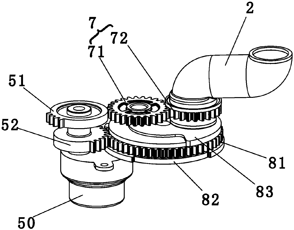
[0040]In this embodiment, the liquid discharge valve includes a mounting shell 85, an upper static valve plate 82 and a lower static valve plate 83 with a static valve hole 84, a planar moving valve plate 81 for opening or closing the static valve hole 84, and a driving discharge valve. The driven assembly 7 that the liquid pipe 2 rotates, wherein, the static valve hole 84 on the upper static valve plate 82 is in sealing communication with the pulping container, and the static valve hole 84 on the lower static valve plate 83 is in sealing communication with the discharge pipe 2, so The plane moving valve plate 81 is only provided with a through communication hole 80, and the static valve hole 84 of the upper static valve plate 82 is set opposite to the static valve hole 84 of the lower s...

Embodiment 2

[0050] like Figure 6 , Figure 7 As shown, it is a schematic structural view of the second embodiment of the drain valve assembly for food processing machines of the present invention. In this embodiment, the first driving device 51 and the second driving device 52 are driven by the same motor 50 to run. The difference between this embodiment and the first embodiment is that the first driving device 51 is a first incomplete gear, the second driving device 52 is a second complete gear, and the planar movable valve plate 81 is driven by the second complete gear, wherein the first While an incomplete gear drives the driven assembly, the second complete gear also synchronously drives the planar movable valve plate 81 to work. When the first incomplete gear rotates to disengage from the driven assembly, the second complete gear continues to drive the planar movable valve plate 81 is rotated until the communication hole 80 communicates with the drain pipe 2 .

[0051] In order to...

Embodiment 3

[0060] Such as Figure 11 Shown is the third embodiment of the drain valve assembly for the food processor of the present invention. The difference between this embodiment and the above embodiments is that in this embodiment, the first driving device 51 is a first complete gear, and the second driving device 52 is a second complete gear. Therefore, the driven assembly rotates synchronously with the planar moving valve plate. Wherein, the first complete gear and the driven assembly form a first complete gear transmission mechanism, and the second complete gear and the planar movable valve plate 81 form a second complete gear transmission mechanism.

[0061] Draining process: such as Figure 12 As shown, when the liquid discharge pipe 2 is at the pulp discharge position above the slurry cup 3, the communication hole of the planar movable valve plate 81 overlaps and communicates with the static valve hole, and the pulp discharge pipe 2 performs the pulp discharge operation. Af...


PUM


Abstract

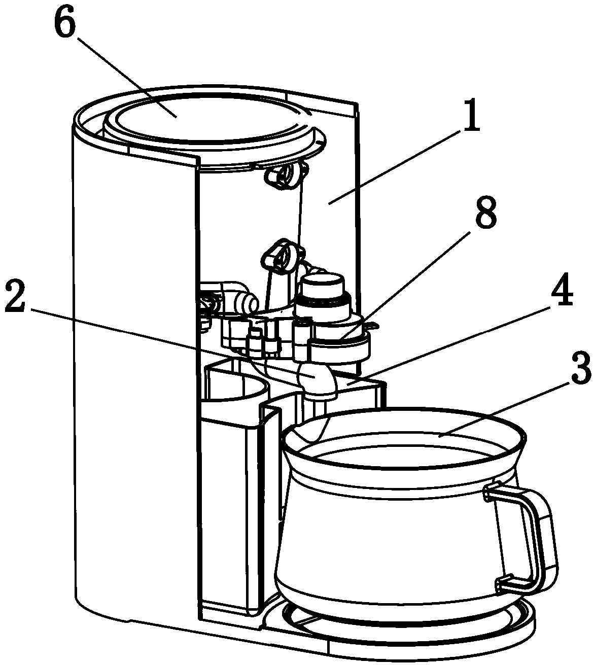
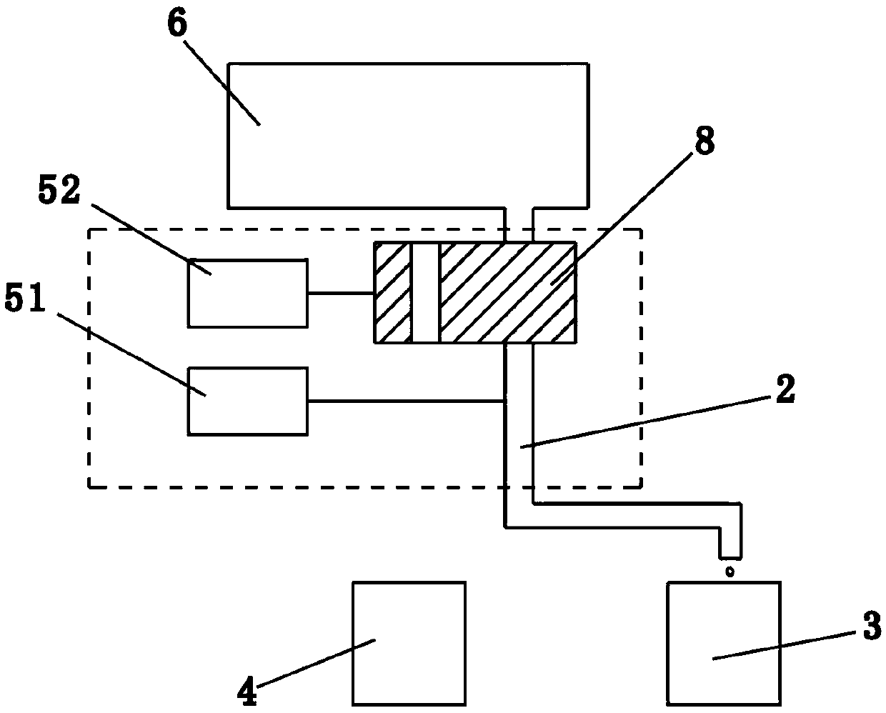
The invention relates to small kitchen household appliances, in particular to a food processing machine with a simple liquid discharging structure. The food processing machine comprises a pulping container, a liquid discharging valve assembly, a pulp receiving cup and a wastewater box, wherein the liquid discharging valve assembly comprises a rotatable liquid discharging pipe, a static valve platewith a static valve hole, a plane movable valve plate for opening or closing the static valve hole, a driven assembly for driving the liquid discharging pipe to rotate, a first driving device for driving the driven assembly to rotate and a second driving device for driving the plane movable valve plate to rotate, the static valve hole communicates with the rear end of the liquid discharging pipein a sealed mode, only one through communication hole is formed in the plane movable valve plate, and when the second driving device drives the plane movable valve plate to move until the communication hole is overlapped with the static valve hole, the pulping container communicates with the liquid discharging pipe. Only one communication hole is formed in the plane movable valve plate, compared with the previous scheme of the applicant, the plane movable valve plate is not prone to storing residues or residual pulp or wastewater, the potential hygiene safety hazard of food is effectively eliminated, the cost is lower, and the structure is simpler and more compact.

Description

technical field [0001] The invention relates to a small kitchen appliance, in particular to a food processor with a simple drain structure. Background technique [0002] The applicant has previously applied for an invention patent application with the patent application number "CN201810006500.4" and the title "a food processing machine". It is disclosed in the patent application that both the movable valve plate and the driven assembly are driven by the driving device driven by the same motor, and the driven assembly and the driven valve plate do not rotate at the same time, wherein the first driving device and the second driving device forming the driving device The device is set as two sets of incomplete gears to realize the simultaneous rotation of the driven assembly and the moving valve plate. Figure 6 It can be clearly seen that the movable valve plate is a valve core with two through holes. When different holes communicate with the communication holes on the static...

Claims


Application Information

Patent Timeline
IPC IPC(8): A47J43/07A47J43/08
CPCA47J43/04A47J43/07Y02A40/90
Inventor 王旭宁郭红伟黄启浪吴艳华
Owner JOYOUNG CO LTD
Learn More