
Automobile engine mounting bracket

A technology for automotive engines and mounting brackets, which is applied in power plants, vehicle maintenance, and vehicle parts, etc. It can solve the problems of wasting manpower and time, inconvenient installation and disassembly, dripping of oil or impurities, etc., to improve cleanliness and facilitate installation And the effect of disassembly, easy maintenance and replacement

Active Publication Date: 2019-07-09
CHONGQING YONGCHUAN DISTRICT BANGWEI MACHINERY MFG CO LTD
View PDF7 Cites 0 Cited by
  • Summary
  • Abstract
  • Description
  • Claims
  • Application Information

AI Technical Summary

Problems solved by technology

[0003] The existing automobile engine rear beam installation bracket structure is usually fixed in structure, which is not convenient for installation and disassembly, and is also not convenient for replacement and maintenance. The disassembly speed is slow, wasting manpower and time, and the use effect is poor. The existing automobile engine rear beam installation The bracket structure is generally poor in functionality. Since the engine will drip oil or impurities on the bracket during use, if it is not cleaned, the engine may move slightly, which will affect the engine's work.

Method used


Image

  • Automobile engine mounting bracket
  • Automobile engine mounting bracket
  • Automobile engine mounting bracket

Examples


Embodiment Construction

[0019] In order to make the technical means, creative features, achievement goals and effects realized by the present invention easy to understand, the present invention will be further described below with reference to the specific embodiments.

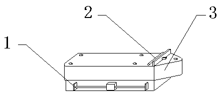
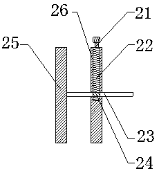
[0020] see Figure 1-Figure 3 , The present invention provides a technical solution: an automobile engine mounting bracket, comprising a disassembly mechanism 1, a cleaning mechanism 2 and a bracket main body 3, the bracket main body 3 is installed on the disassembly mechanism 1, and the cleaning mechanism 2 is arranged on the upper end face of the bracket main body 3, The cleaning mechanism 2 is provided on the upper side of the dismounting mechanism 1 .

[0021] The dismantling mechanism 1 includes a connecting block 11, a screw rod 12, a connecting rod 13, a base 14, a spring 15 and a guide tube 16. The connecting block 11 is installed on the screw rod 12, and the rear end of the connecting block 11 is provided with a connecting r...


PUM


Abstract

The invention provides an automobile engine mounting bracket which comprises a connecting block, a lead screw, a connecting rod, a base, a spring, a guide tube, a miniature motor, a rotating shaft, arack, a circular gear, a cleaning rod and a supporting plate. The connecting block is mounted on the lead screw; the connecting rod is arranged at the rear end of the connecting block, the spring is mounted at the rear end of the connecting rod and is placed at the rear end in the guide tube, and the connecting rod is placed on the guide tube. The automobile engine mounting bracket is convenient to disassemble, the miniature motor is mounted on the rear side of the supporting plate, the rack is arranged on the supporting plate, the circular gear is arranged at the lower end of the rack, a rotating shaft is arranged on the circular gear, the miniature motor is arranged at the rear end of the rotating shaft, a cleaning rod is arranged at the left end of the rack, and the cleaning rod is mounted on the left side of the supporting plate. The automobile engine mounting bracket is convenient to clean, convenient to use and operate, good in stability, high in reliability, convenient to disassemble and convenient to clean.

Description

technical field [0001] The invention relates to an automobile engine mounting bracket, which belongs to the field of automobile engine beam mounting bracket equipment. Background technique [0002] The rear crossbeam of an automobile engine is a bracket for installing and fixing the engine, which ensures the stability of the engine. [0003] The existing automobile engine rear beam mounting bracket structure is usually fixed in structure, which is inconvenient for installation and disassembly, and also inconvenient for replacement and maintenance, slow disassembly, waste of manpower and time, and poor use effect. The existing automobile engine rear beam installation The structure of the bracket is generally poor in functionality. Since the engine will drip oil or impurities on the bracket during use, if it is not removed, it may cause the engine to move slightly, thereby affecting the operation of the engine. SUMMARY OF THE INVENTION [0004] In view of the deficiencies i...

Claims


Application Information

Patent Timeline
Patent Type & Authority Applications(China)
IPC IPC(8): B60K5/12B60S1/62
CPCB60K5/12B60S1/62
Inventor 彭芝英
Owner CHONGQING YONGCHUAN DISTRICT BANGWEI MACHINERY MFG CO LTD
Learn More