
Multi-surface machining mechanism for milling machine

A multi-face machining and milling machine technology, applied in milling machines, milling machine equipment, metal processing equipment, etc., can solve the problems of complex process, high cost, and inability to process the sides.

Pending Publication Date: 2019-07-09
XUZHOU COLLEGE OF INDAL TECH
View PDF0 Cites 0 Cited by
  • Summary
  • Abstract
  • Description
  • Claims
  • Application Information

AI Technical Summary

Problems solved by technology

[0002] The traditional vertical CNC milling machine has a high share in the whole market. It is mainly used to process box-type parts, but there are the following problems: when the upper surface of the part is processed in one clamping, the side cannot be processed. On the side, multiple clamping and special fixtures are required to realize multi-side machining, and sometimes even a five-axis machining center is required for machining, which is complicated and expensive

Method used


Image

  • Multi-surface machining mechanism for milling machine
  • Multi-surface machining mechanism for milling machine
  • Multi-surface machining mechanism for milling machine

Examples


Embodiment Construction

[0025] In order to make the object, technical solution and advantages of the present invention clearer, the present invention will be further described in detail below. However, it should be understood that the specific embodiments described here are only used to explain the present invention, and are not intended to limit the scope of the present invention.

[0026] Unless otherwise defined, all technical terms and scientific terms used herein have the same meaning as commonly understood by those skilled in the technical field of the present invention, and the terms used in the description of the present invention herein are only to describe specific implementations The purpose of the example is not intended to limit the present invention.

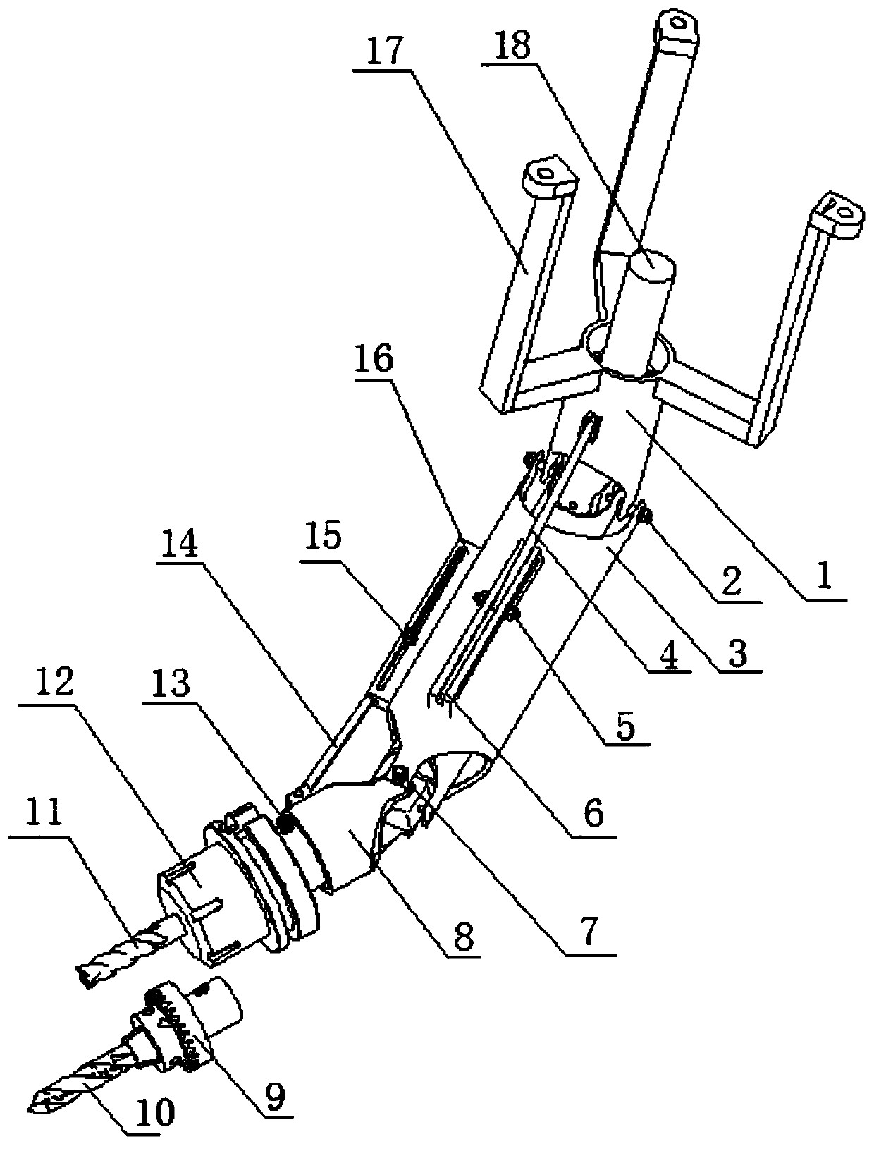
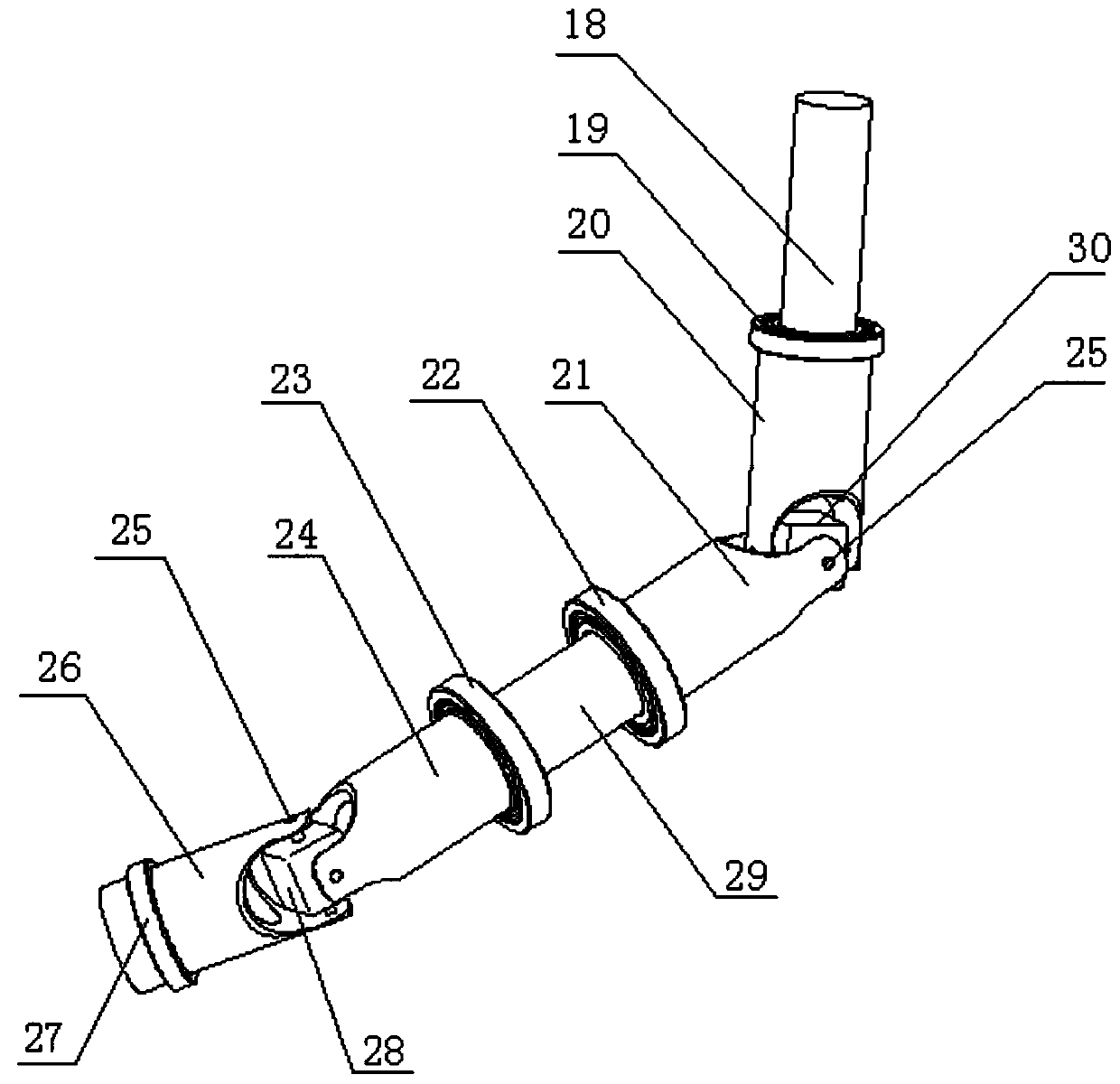
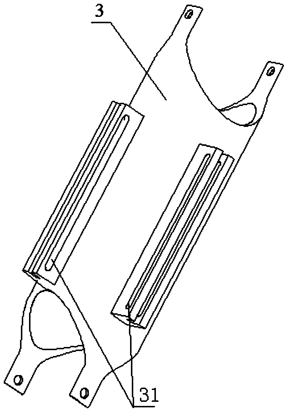
[0027] Such as figure 1 , figure 2 Shown, a kind of multi-face machining mechanism for milling machine comprises upper shell 1, middle shell 3, lower shell 8 and hole processing assembly, the bottom end of described upper shell 1 is co...


PUM


Abstract

The invention discloses a multi-surface machining mechanism for a milling machine. The multi-surface machining mechanism for the milling machine comprises an upper shell, a middle shell, a lower shelland a hole machining assembly, wherein the bottom end of the upper shell is connected with the top end of the middle shell; the bottom end of the middle shell is connected with the top end of the lower shell; the bottom end of the lower shell is connected with the hole machining assembly; positioning mechanisms are respectively arranged between the upper shell and the middle shell and between themiddle shell and the lower shell; an upper transmission shaft, an upper bearing and an upper connecting piece are arranged in the upper shell and are sequentially connected; a first connecting piece,a first bearing, a lower transmission shaft, a second bearing and a second connecting piece aree arranged in the middle shell and are sequentially connected; a lower connecting piece and a lower bearing are arranged in the lower shell and are sequentially connected; the upper connecting piece is movably connected with the first connecting piece; and the second connecting piece is movably connected with the lower connecting piece. The multi-surface machining mechanism has the advantages that the angles are conveniently adjusted, multi-angle machining on the side surface of a part is achieved,the operation is simple and safe, the precision is remarkably improved, and the production cost is reduced.

Description

technical field [0001] The invention relates to a multi-face processing mechanism for a milling machine, which belongs to the field of milling machine processing equipment. Background technique [0002] The traditional vertical CNC milling machine has a high share in the whole market. It is mainly used to process box parts, but there are the following problems: when the upper surface of the part is processed in one clamping, the side cannot be processed. On the side, multiple clamping and special fixtures are required to realize multi-side machining, and sometimes even a five-axis machining center is required for machining, which is complex and expensive. Contents of the invention [0003] Aiming at the above-mentioned problems in the prior art, the present invention provides a multi-face machining mechanism for milling machines, which can be manually adjusted to reach the corresponding surface of the workpiece, and then cooperate with the CNC milling machine to process an...

Claims


Application Information

Patent Timeline
Patent Type & Authority Applications(China)
IPC IPC(8): B23C1/12
CPCB23C1/12
Inventor 徐敏姜海林颜光稳沈嘉诚杨权权蒋文怡
Owner XUZHOU COLLEGE OF INDAL TECH
Learn More