A Waveform Inversion Method for Reflected Waveform Constrained by Smoothness along Stratum Strike
A waveform inversion and smooth constraint technology, applied in the field of oil and gas exploration, can solve the problem of poor stability of reflected wave waveform inversion
- Summary
- Abstract
- Description
- Claims
- Application Information
AI Technical Summary
Problems solved by technology
Method used
Image
Examples
Embodiment 1
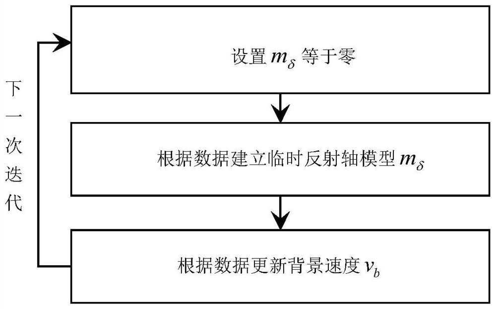
[0070] Embodiment 1 provides a smooth-constrained reflection wave waveform inversion method along the stratum strike, the reflection wave waveform inversion method includes the following steps:
[0071] Step A: Select the initial background velocity model v b , set the termination error ∈, the maximum number of iterations k, and set up the expression to minimize the objective function φ as follows:
[0072]
[0073] u in formula 1 δ represents the predicted reflected wave field, R represents the geophone operator used to extract the record of the receiver point from the reflected wave field, d represents the actually observed record, v b represents the background velocity, m δ represents the reflection axis model;
[0074] Step B: Set reflection axis model m δ = 0;
[0075] Step C: Calculate the temporary reflection axis model m δ , including the following steps:
[0076] Step C1: Minimize the objective function with respect to the reflection axis model m δ gradient...
Embodiment 2
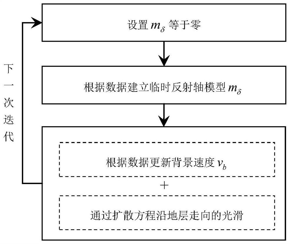
[0115] Embodiment 2 integrates the diffusion equation in Embodiment 1 into the minimized objective function φ to form a new objective equation, and the expression of this new objective equation is:
[0116]
[0117] In formula 6, is the anti-smooth operator along the formation interface, such as the difference operator along the interface; μ 2 is the weighting coefficient.
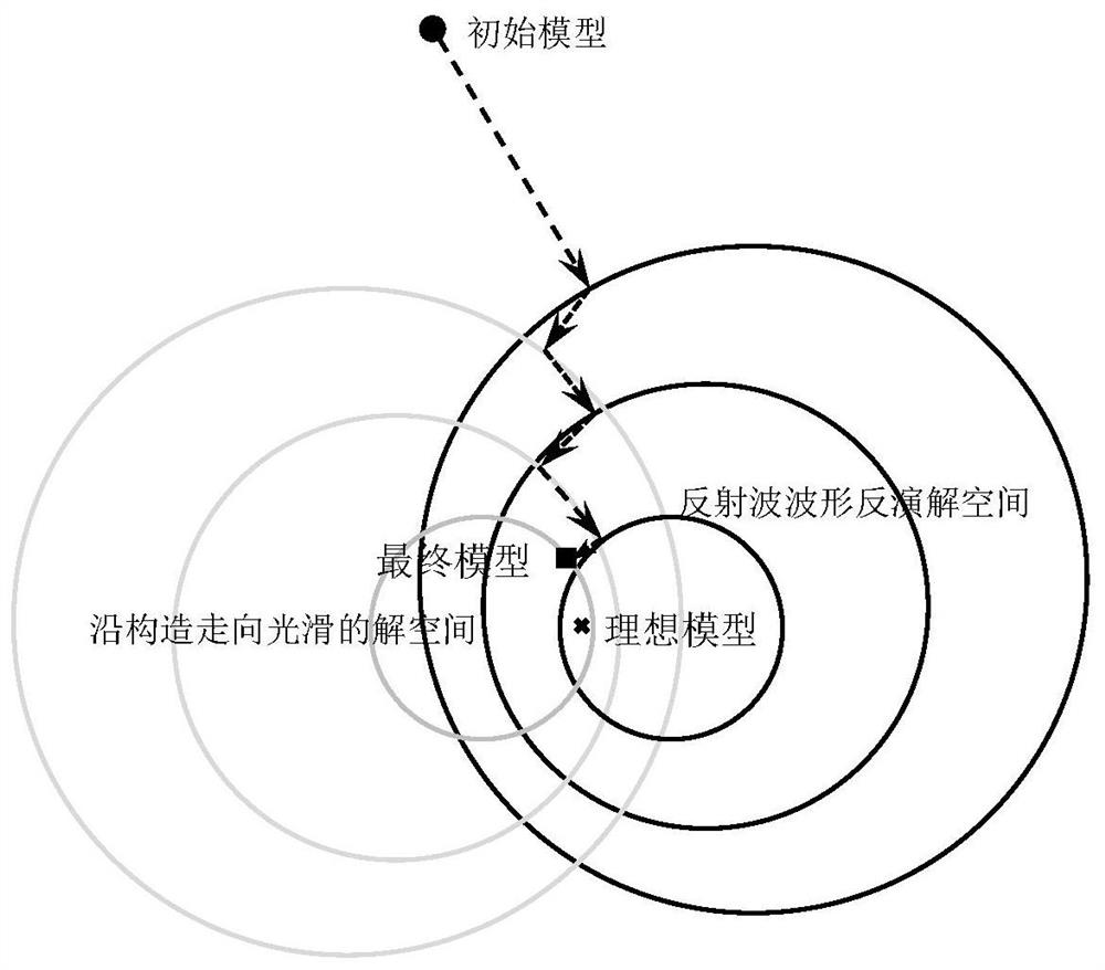
[0118] Therefore, the wave equation (Equation 2) and the new objective equation (Equation 6) can be used to construct a smooth-constrained reflected wave waveform inversion system along the formation strike. Step A, step B, step C and step E are the same as in embodiment 1, the difference is that in step D, the background velocity model v is updated according to the gradient calculation of the new objective function (Formula 6) b , at the same time, in order to eliminate the columnar and spherical false anomalies produced by the inversion of the unconstrained reflected wave waveform, a new gradient g...
PUM
 Abstract
Description
Claims
Application Information
 - R&D
- Intellectual Property
- Life Sciences
- Materials
- Tech Scout
- Unparalleled Data Quality
- Higher Quality Content
- 60% Fewer Hallucinations
Browse by: Latest US Patents, China's latest patents, Technical Efficacy Thesaurus, Application Domain, Technology Topic, Popular Technical Reports.
© 2025 PatSnap. All rights reserved.Legal|Privacy policy|Modern Slavery Act Transparency Statement|Sitemap|About US| Contact US: help@patsnap.com


