Optical signal receiving system, method and laser radar

A receiving system and optical signal technology, applied in the field of optics, can solve problems such as lidar sensitivity drop, lidar scanning blind area, etc., to achieve the effects of reducing interference, improving receiving ability, and improving sensitivity

Active Publication Date: 2021-08-17
SUTENG INNOVATION TECH CO LTD
View PDF6 Cites 0 Cited by
  • Summary
  • Abstract
  • Description
  • Claims
  • Application Information

AI Technical Summary

Problems solved by technology

However, as the sensitivity of the receiving element increases, it brings engineering problems. While the sensitive receiving element improves the response to the weak reflected light signal, it also improves the response to the reflected light signal of the target object near the laser radar. , such as the response from the transmitting system to stray light generated internally by the lidar
[0004] These stray lights are responded by sensitive receiving components, causing the scanning blind area of ​​the lidar, which reduces the sensitivity of the lidar

Method used


Image

  • Optical signal receiving system, method and laser radar
  • Optical signal receiving system, method and laser radar
  • Optical signal receiving system, method and laser radar

Examples


Embodiment Construction

[0040] In order to make the purpose, technical solution and advantages of the present application clearer, the present application will be further described in detail below in conjunction with the accompanying drawings and embodiments. It should be understood that the specific embodiments described here are only used to explain the present application, and are not intended to limit the present application.

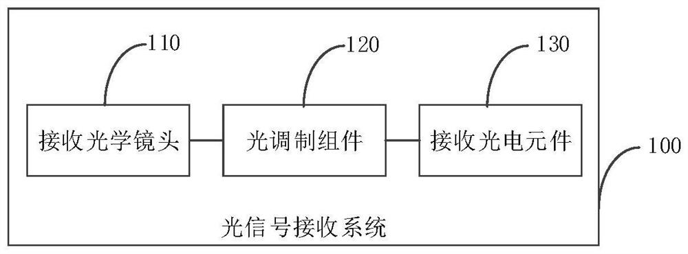
[0041] figure 1 A schematic structural diagram of an optical signal receiving system provided by an embodiment. The system 100 includes: a receiving optical lens 110, which is used to couple the collected optical signal into a light modulation component 120; a light modulation component 120, which is used to control whether the light signal enters the receiving photoelectric element 130 according to the set timing; the receiving photoelectric element 130, configured to respond to the incident optical signal.

[0042] Specifically, the above optical signal receiving syste...


PUM


Abstract

The present application relates to an optical signal receiving system, method and laser radar. The system includes: a receiving optical lens, used to couple the collected optical signal into the light modulation component; the light modulation component, used to control whether the light signal enters the receiving photoelectric element according to the set timing; the receiving photoelectric element, for responding to the incident light signal. The system can greatly reduce the stray light entering the system, thereby greatly reducing the interference of stray light to the system, greatly improving the sensitivity of the optical signal receiving system, and thus greatly improving the receiving ability of the radar.

Description

technical field [0001] The present application relates to the field of optical technology, in particular to an optical signal receiving system, method and laser radar. Background technique [0002] With the development of lidar technology, people have higher and higher requirements for the detection performance of lidar. [0003] The traditional LiDAR is based on the Time of Flight Measurement (TOF) principle and consists of a transmitting system, a receiving system, and an information processing system. The receiving system of the laser radar receives the reflected light signal reflected by the target object. As the target distance increases, the intensity of the reflected light signal decreases. Therefore, extremely sensitive optoelectronic components are required as the receiving element. However, as the sensitivity of the receiving element increases, it brings engineering problems. While the sensitive receiving element improves the response to the weak reflected light s...

Claims


Application Information

Patent Timeline
Patent Type & Authority Patents(China)
IPC IPC(8): G01S7/481
CPCG01S7/4816G01S7/4818
Inventor 魏威
Owner SUTENG INNOVATION TECH CO LTD
Why Eureka
Try Eureka