Robot charging method, device and robot
A charging method and charging device technology, applied in the field of robotics, can solve problems such as high cost, affecting charging efficiency, and long time consumption, and achieve the effects of improving accuracy, improving charging efficiency, and shortening charging time
- Summary
- Abstract
- Description
- Claims
- Application Information
AI Technical Summary
Problems solved by technology
Method used
Image
Examples
Embodiment 1
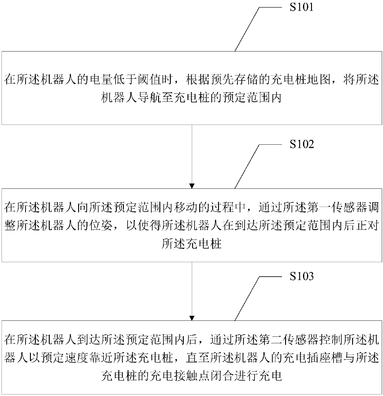
[0031] figure 1 It shows a schematic diagram of the implementation process of the robot charging method provided by the first embodiment of the present invention. The robot includes its own first sensor and second sensor. The robot charging method may include:
[0032] Step S101: When the power of the robot is lower than a threshold, navigate the robot to a predetermined range of a charging pile according to a pre-stored charging pile map.
[0033] In an embodiment of the present invention, the charging pile map includes location information of at least one charging pile. When there are multiple charging piles, the charging pile with the closest distance, the charging pile with the fastest charging speed, or the charging pile with the most convenient charging can be selected. After selecting the charging pile, use the fixed-point navigation system of the robot to navigate the robot to the predetermined range of the selected charging pile.
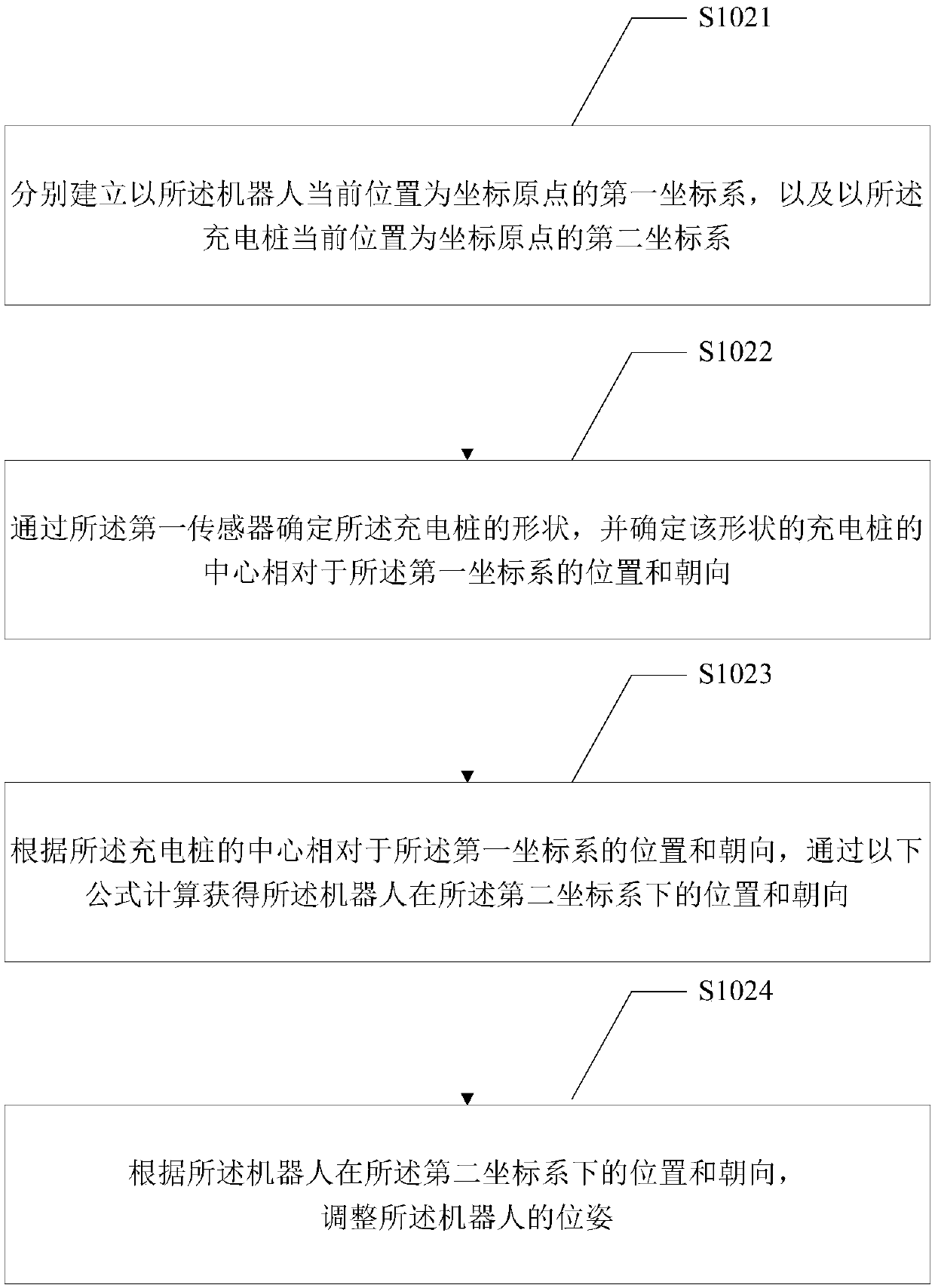
[0034] Step S102: During the proce...
Embodiment 2
[0051] In order to simplify the adjustment process of the robot in the first embodiment to adjust the pose of the robot so that the robot is facing the charging pile after reaching the predetermined range, the second embodiment of the present invention provides another robot charging method:
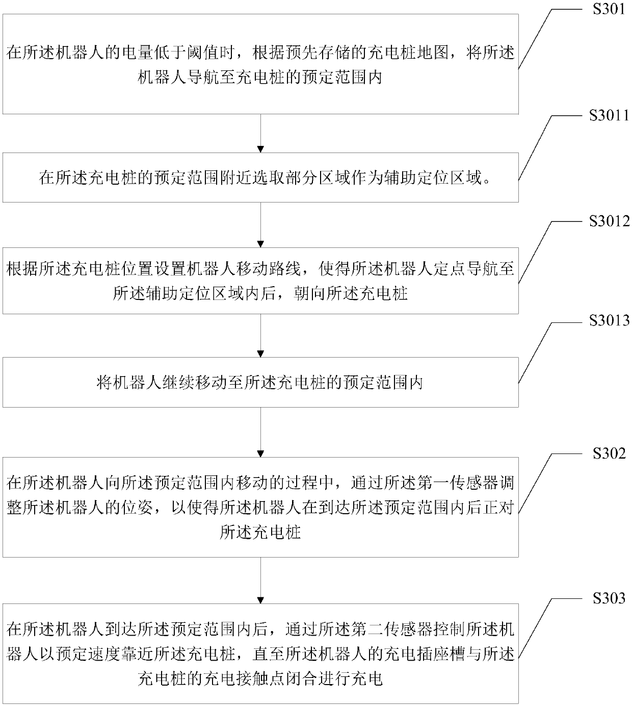
[0052] The step S101 of the robot charging method provided in the first embodiment also includes: selecting a part of the area within the predetermined range as an auxiliary positioning area; setting the moving route of the robot according to the position of the charging pile, so that the robot can navigate to After entering the auxiliary positioning area, it faces the charging pile.
[0053] Such as image 3 Shown:
[0054] A robot charging method, the robot includes a first sensor and a second sensor, the robot charging method includes:
[0055] Step S301: When the battery power of the robot is lower than a threshold, navigate the robot to a predetermined range of a charging pile ac...
Embodiment 3
[0067] Figure 4 It is a schematic diagram of the actual application scene of the robot charging method in the second embodiment provided by the embodiment of the present invention, Figure 5 is in Figure 4 The specific flow chart of the robot charging method in the second embodiment is provided on the basis of the application scenario.
[0068] Such as Figure 4 As shown, the map of the charging pile is shown as a sector with a radius of 170 cm and an included angle of 90°; the predetermined range of the charging pile is 50 cm in front of the charging pile; an auxiliary positioning area is set outside the predetermined range. The auxiliary positioning area is set in the fan-shaped area on the front of the charging pile 70 cm away and within 170 cm.
[0069] Figure 5 The specifics of the robot charging method shown may include:
[0070] 1. Monitor the battery power of the robot. If the power is lower than the threshold, the autonomous charging task will be started.
[...
PUM
 Abstract
Description
Claims
Application Information
 - Generate Ideas
- Intellectual Property
- Life Sciences
- Materials
- Tech Scout
- Unparalleled Data Quality
- Higher Quality Content
- 60% Fewer Hallucinations
Browse by: Latest US Patents, China's latest patents, Technical Efficacy Thesaurus, Application Domain, Technology Topic, Popular Technical Reports.
© 2025 PatSnap. All rights reserved.Legal|Privacy policy|Modern Slavery Act Transparency Statement|Sitemap|About US| Contact US: help@patsnap.com


