A method, device and terminal for relocating target points on a map

A target point, relocation technology, applied in the field of navigation data, can solve the problems of map software accuracy loss, positioning error, etc., to achieve the effect of strong reusability, reducing deviation, and simplifying coordinate conversion steps

Active Publication Date: 2021-05-25
ZHEJIANG GEELY AUTOMOBILE RES INST CO LTD +1
View PDF0 Cites 0 Cited by
  • Summary
  • Abstract
  • Description
  • Claims
  • Application Information

AI Technical Summary

Problems solved by technology

[0006] The technical problem to be solved by the present invention is the problem of accuracy loss and positioning error when map software converts

Method used


Image

  • A method, device and terminal for relocating target points on a map
  • A method, device and terminal for relocating target points on a map
  • A method, device and terminal for relocating target points on a map

Examples


Embodiment 1

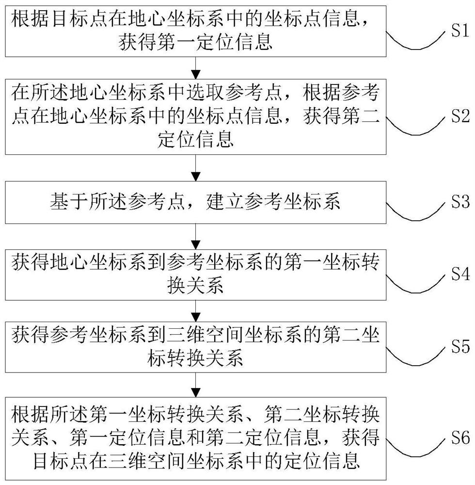
[0063] An embodiment of the present invention provides a method for locating a target point on a map, such as figure 1 As shown, the method includes:

[0064] S1. Obtain first positioning information according to the coordinate point information of the target point in the geocentric coordinate system.

[0065] Specifically, the geocentric coordinate system is an ECEF coordinate system, and the origin (0, 0, 0) of the ECEF coordinate system is defined as the center of mass of the earth.

[0066] The z-axis of the ECEF coordinate system extends through true north, which does not coincide with the instantaneous Earth rotation axis. The x-axis of the ECEF coordinate system intersects the earth at 0° latitude and 0° longitude, so the ECEF coordinate system rotates with the earth, so the coordinates of points fixed on the earth's surface do not change.

[0067] In a specific embodiment, the three-dimensional space coordinate system is defined as selecting one point in the area as ...

Embodiment 2

[0100] An embodiment of the present invention provides a device for locating target points on a map, such as Figure 5 As shown, the device includes: a geocentric coordinate system data storage module 201, a reference coordinate system establishment module 202 and a relocation module 203;

[0101] The geocentric coordinate system data storage module 201 is used to store coordinate point information in the geocentric coordinate system, and the coordinate point information includes first positioning information corresponding to the coordinates of the reference point, and second positioning information corresponding to the coordinates of the target point;

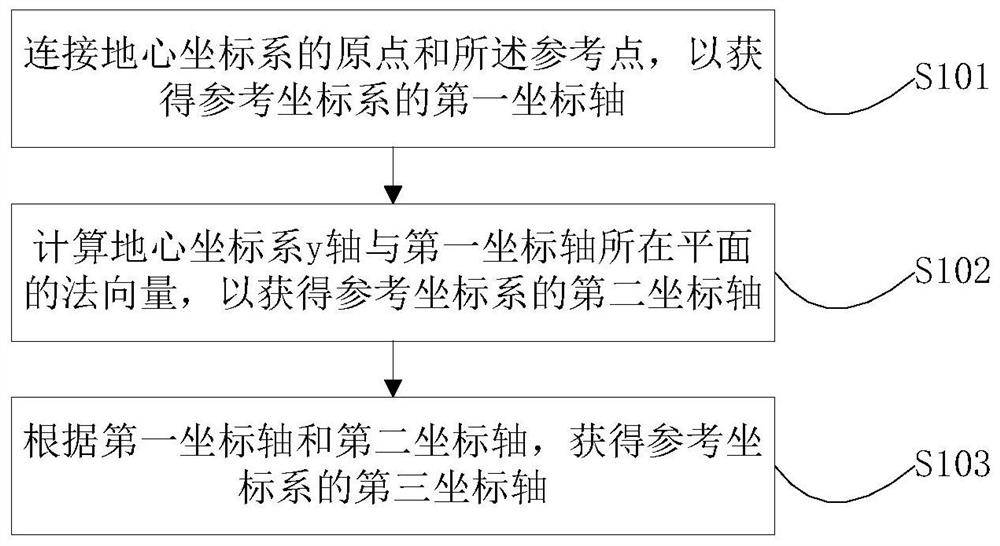
[0102] The reference coordinate system establishment module 202 is used to establish a reference coordinate system based on the reference point;

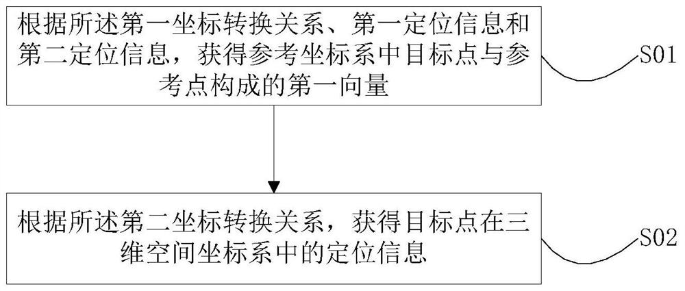
[0103] The relocation module 203 is used to convert the location information of the target point from the geocentric coordinate system to the three-dimensional space coordinate syst...

Embodiment 3

[0130] An embodiment of the present invention provides a terminal, and the terminal includes the above-mentioned device for locating a target point on a map.


PUM


Abstract

The invention relates to the field of navigation data, and provides a method, device and terminal for relocating target points on a map. The method includes selecting a reference point in a geocentric coordinate system and establishing a reference coordinate system. Obtain the first coordinate transformation relationship from the earth-centered coordinate system to the reference coordinate system, obtain the second coordinate transformation relationship from the reference coordinate system to the three-dimensional space coordinate system, according to the positioning information of the reference point and the target point in the earth-centered coordinate system, and the first A coordinate conversion relationship, obtaining vector information from a reference point to a target point in the reference coordinate system, converting the vector information through a second coordinate conversion relationship, and obtaining positioning information of the target point in the three-dimensional space coordinate system. This method converts the coordinate points of the reference coordinate system and the coordinate points of the three-dimensional space coordinate system, unifies the coordinate system type, simplifies the coordinate conversion steps and eliminates the participation of constants such as earth ellipsoid parameters in the conversion, and reduces the relative distance between objects in adjacent areas. Position offset due to conversion.

Description

technical field [0001] The invention relates to the field of navigation data, in particular to a method, device and terminal for relocating target points on a map. Background technique [0002] For self-driving vehicles, high-precision maps can provide map data with more accurate coordinates, so that the automatic driving system can obtain more accurate information when controlling the vehicle. Therefore, high-precision maps are one of the core technologies of unmanned driving. First, accurate maps are crucial to the positioning, navigation and control, and safety of unmanned vehicles. [0003] In the link of using computer technology to simulate and render real scenes to obtain highly simulated video data, limited by the coordinate setting of the rendering engine, the performance of the device, and the real needs of the amount of scenes used, it is impossible to directly use geographic location information to locate in the virtual space Restoring the scene in the virtual 3...

Claims


Application Information

Patent Timeline
Patent Type & Authority Patents(China)
IPC IPC(8): G01C21/30
CPCG01C21/30
Inventor 周蕴嘉
Owner ZHEJIANG GEELY AUTOMOBILE RES INST CO LTD
Why Eureka
Try Eureka