
Radio frequency transmitting terminal, and application site, power control method and system thereof

A technology of radio frequency transmission and power control, which is applied in power management, short-distance communication services, wireless communication, etc., and can solve problems such as unreachable operation, smaller terminal operating distance, and fixed terminal 1 misoperation to vehicles on lane 5, etc.

Inactive Publication Date: 2019-07-02
广州朗昇网络科技有限公司
View PDF3 Cites 2 Cited by
  • Summary
  • Abstract
  • Description
  • Claims
  • Application Information

AI Technical Summary

Problems solved by technology

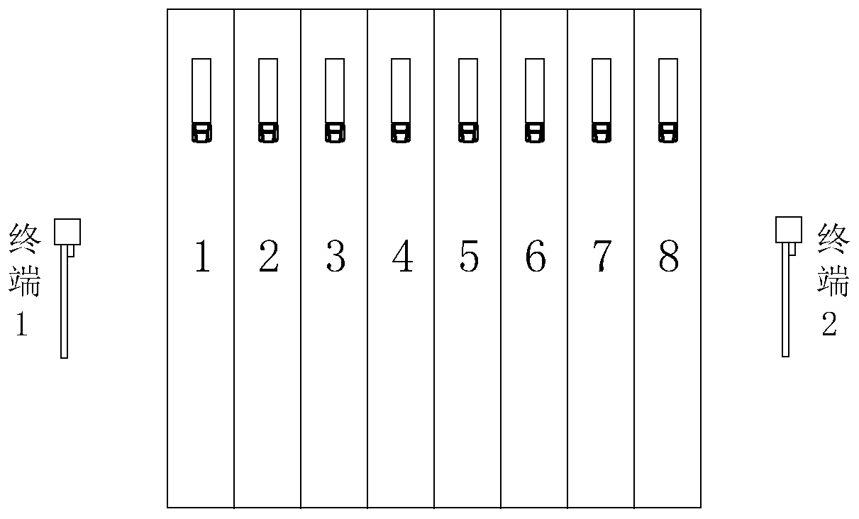
In actual use, sometimes the fixed terminal 1 may misoperate to the vehicle above lane 5, or the terminal 2 may misoperate to the vehicle above lane 3; however, various reasons will affect the transmission of RFID signals, so that the operating distance of the terminal becomes smaller. Small, sometimes less than lane 4 or lane 5

Method used


Image

  • Radio frequency transmitting terminal, and application site, power control method and system thereof
  • Radio frequency transmitting terminal, and application site, power control method and system thereof
  • Radio frequency transmitting terminal, and application site, power control method and system thereof

Examples


Embodiment Construction

[0049] The following will clearly and completely describe the technical solutions in the embodiments of the present invention with reference to the accompanying drawings in the embodiments of the present invention. Obviously, the described embodiments are only some, not all, embodiments of the present invention. Based on the embodiments of the present invention, all other embodiments obtained by persons of ordinary skill in the art without making creative efforts belong to the protection scope of the present invention.

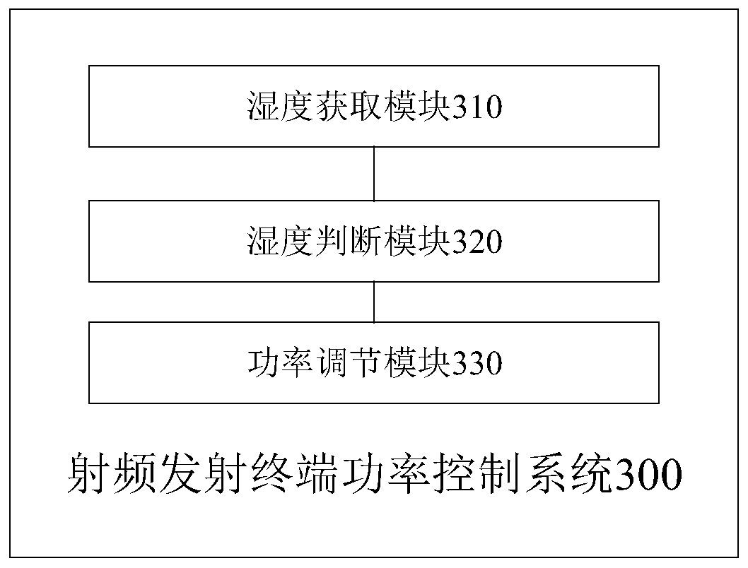
[0050] Please refer to figure 2 , figure 2 It is a flow chart of a radio frequency transmitting terminal power control method provided by a specific embodiment of the present invention.

[0051] In a specific implementation manner of the present invention, an embodiment of the present invention provides a radio frequency transmitting terminal power control method, including:

[0052] Step S11: Obtain the current real-time humidity value;

[0053] Step S12: ...


PUM


Abstract

The invention provides a radio frequency transmitting terminal and an application site thereof, and a power control method and system, and the method comprises the steps: obtaining a current real-timehumidity value; judging whether the current real-time humidity value is consistent with a current preset humidity value or not; if the current real-time humidity value is not consistent with the current preset humidity value, adjusting the transmitting power of the radio frequency transmitter, so that the maximum radio frequency identification distance of the radio frequency transmitter is between a first preset distance and a second preset distance; wherein the first preset distance is smaller than the second preset distance. The invention provides a radio frequency transmitting terminal power control method. According to the invention, when the current real-time humidity value changes, the transmitting power of the radio frequency transmitter can be adjusted in time, and the maximum radio frequency identification distance is controlled between the first preset distance and the second preset distance, so that wireless radio frequency communication can be controlled within a set range, and power waste and communication interference are avoided.

Description

technical field [0001] The present invention relates to the technical field of electronic identification equipment, in particular to a radio frequency transmitting terminal and its application site, power control method and system. Background technique [0002] Radio frequency identification, RFID (Radio Frequency Identification) technology, also known as radio frequency identification, is a communication technology that can identify specific targets through radio signals and read and write related data without the need to establish mechanical or optical contact between the identification system and specific targets . In the use of radio frequency in the prior art, the radio frequency system generally includes radio frequency transmitting terminals and electronic tags. At present, RFID technology is widely used, such as: libraries, access control systems, food safety traceability, etc. [0003] However, the transmitting power of the wireless radio frequency terminal in the ...

Claims


Application Information

Patent Timeline
IPC IPC(8): H04W52/28H04W4/80
CPCH04W52/28H04W4/80
Inventor 余志坤任美云方咏娴郭伟沂
Owner 广州朗昇网络科技有限公司
Learn More