Electronic stability control system test method and test device

A technology of electronic stability control and testing equipment, which is applied in the general control system, control/regulation system, test/monitoring control system, etc., can solve the problems of not being able to simulate the test effect of the real vehicle state, and the direct measurement cannot be realized, etc., to achieve Achieve full-featured testing, improve test accuracy and consistency

Pending Publication Date: 2019-07-02
上海顺试汽车科技有限公司
View PDF0 Cites 1 Cited by
  • Summary
  • Abstract
  • Description
  • Claims
  • Application Information

AI Technical Summary

Problems solved by technology

The equivalent simulation in the laboratory state cannot be carried out for the anti-lock braking system ABS, brake clamping force distribution, brake assist, traction control, etc.
The direct measurement of brake fluid pressure, caliper clamping force, etc. cannot be realized, and the parameters can only be converted based on the virtual vehicle, and the test effect of simulating the state of the real vehicle cannot be obtained.

Method used


Image

  • Electronic stability control system test method and test device
  • Electronic stability control system test method and test device
  • Electronic stability control system test method and test device

Examples


Embodiment Construction

[0076] Preferred embodiments of the present invention will be described in detail below with reference to the accompanying drawings, so as to better understand the purpose, features and advantages of the present invention. It should be understood that the embodiments shown in the drawings are not intended to limit the scope of the present invention, but only to illustrate the essence of the technical solutions of the present invention.

[0077] In the following description, for the purposes of explaining the various disclosed embodiments, certain specific details are set forth in order to provide a thorough understanding of the various disclosed embodiments. One skilled in the relevant art will recognize, however, that an embodiment may be practiced without one or more of these specific details. In other instances, well-known devices, structures and techniques associated with the present application may not have been shown or described in detail in order to avoid unnecessarily...


PUM


Abstract

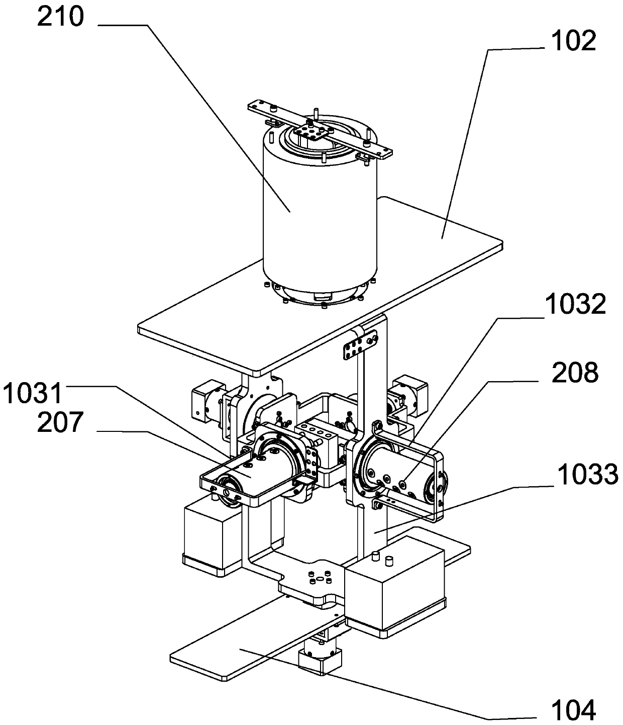
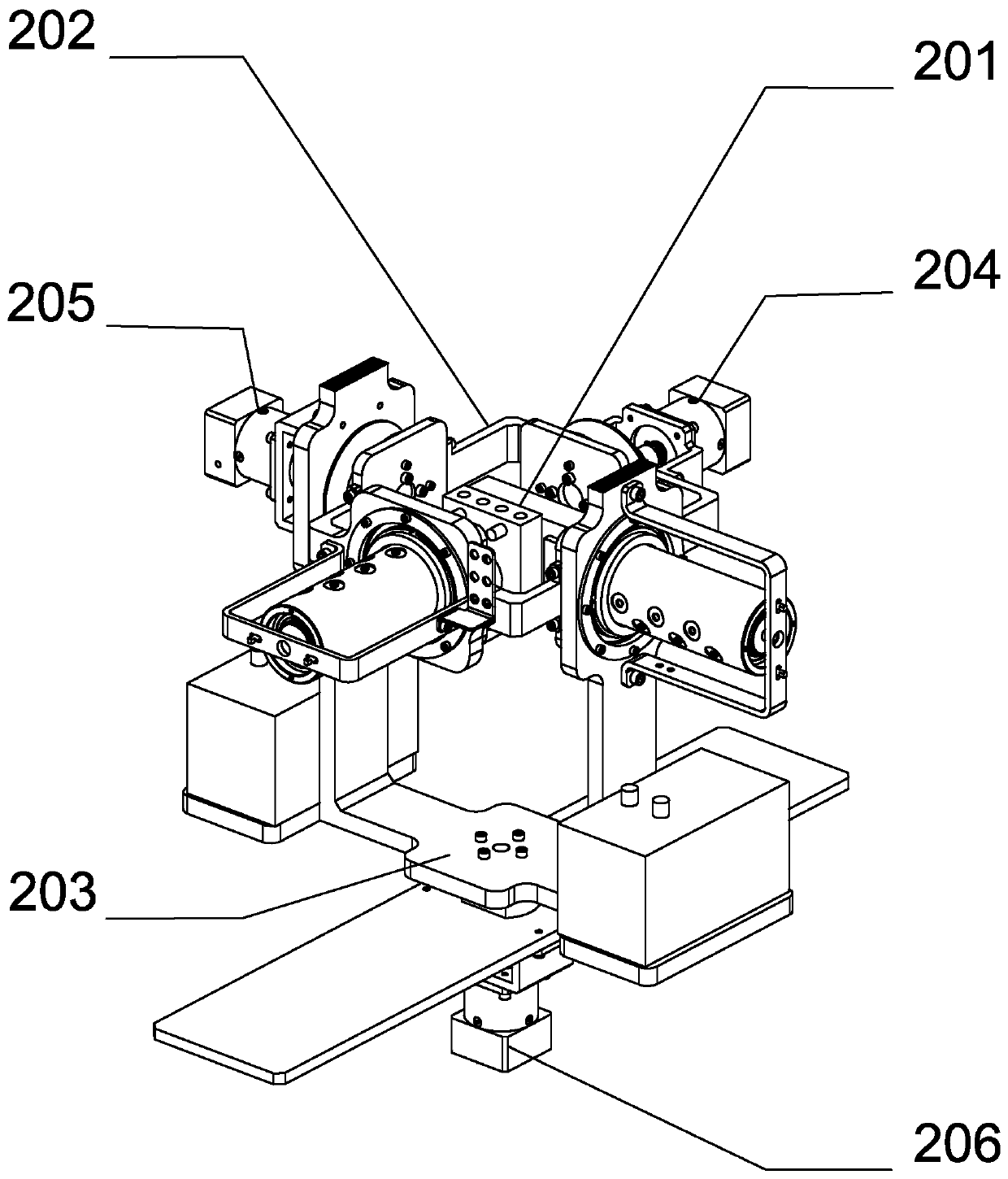
The invention provides a test device which comprises a mounting frame, an X-axis rotating device which comprises an X-axis rotating driving assembly, an X-axis supporting frame and an X-axis rotatinghydraulic joint, a Y-axis rotating device which comprises a Y-axis rotating driving assembly, a Y-axis supporting frame and a Y-axis rotating hydraulic joint, a Z-axis rotating device which comprisesa Z-axis rotating driving assembly, a Z-axis supporting frame and a Z-axis rotating hydraulic joint, a first set of hydraulic lines which connect the outer ring flow path of the X-axis rotating hydraulic joint and the inner ring flow path of the Y-axis rotating hydraulic joint, and a second set of hydraulic lines which connect the outer ring flow path of the Y-axis rotating hydraulic joint and theinner ring flow path of the Z-axis rotating hydraulic joint. The invention further provides a test method which uses the test device. According to the invention, the test device and method can simulate and test the true state of a test piece and actually test the hydraulic lines associated therewith.

Description

technical field [0001] The technical invention relates to an electronic stability control system (also referred to as ESC, ESP, etc., hereinafter referred to as ESC) testing method and testing device. Background technique [0002] Electronic stability control system (also known as ESC, ESP, VSC, DTSC, etc.) is a new type of active safety system for vehicles. Control the driving force and brake clamping force of the front, rear, left and right wheels to ensure the lateral stability of the vehicle. [0003] With the rapid development of the automobile industry, the requirements for component testing are becoming more and more stringent, and it is often necessary to simulate the real driving state of the vehicle. [0004] The test object targeted by the present invention is the electronic stability control system. The electronic stability control system belongs to the active safety configuration of the car. When the vehicle is driving, it actively senses the movement state of...

Claims


Application Information

Patent Timeline
Patent Type & Authority Applications(China)
IPC IPC(8): G05B23/02
CPCG05B23/0243G05B2219/24065
Inventor 张贵民沈建奇谭峰
Owner 上海顺试汽车科技有限公司
Why Eureka
Try Eureka