
Active pulsation attenuation device

A technology of pulsation attenuation and accommodating holes, which is applied in the direction of pipes/pipe joints/fittings, mechanical equipment, pipe components, etc., can solve the problems of low reliability, limited power adjustment range, poor muffler application range, etc. Vibration and noise reduction, expanding the scope of application, and achieving the effect of vibration and noise reduction

Active Publication Date: 2019-07-02
NAVAL UNIV OF ENG PLA
View PDF5 Cites 1 Cited by
  • Summary
  • Abstract
  • Description
  • Claims
  • Application Information

AI Technical Summary

Problems solved by technology

The above-mentioned active muffler can control the pulsation noise of the fluid in the pipe to a certain extent, but it also has certain defects and application limitations, which are mainly reflected in: the above-mentioned active muffler introduces secondary pulsation through the deformation of the pipeline, and its actuation The muffler needs to do extra work to overcome the deformation of the pipe wall, the power conversion efficiency is low, and the power adjustment range is also limited, which leads to the poor application range of the above-mentioned muffler; at the same time, the maintenance of the above-mentioned active muffler is difficult during use, and the reliability of use is relatively low. Low, once the actuator fails, the active muffler will fail, and the replacement and maintenance of the actuator is extremely inconvenient
Therefore, the existing active pulsation attenuators cannot fully meet the needs of the application, and there are certain defects and limitations

Method used


Image

  • Active pulsation attenuation device
  • Active pulsation attenuation device
  • Active pulsation attenuation device

Examples


Embodiment Construction

[0032]In order to make the object, technical solution and advantages of the present invention clearer, the present invention will be further described in detail below in conjunction with the accompanying drawings and embodiments. It should be understood that the specific embodiments described here are only used to explain the present invention, not to limit the present invention.

[0033] In addition, the technical features involved in the various embodiments of the present invention described below can be combined with each other as long as they do not constitute a conflict with each other.

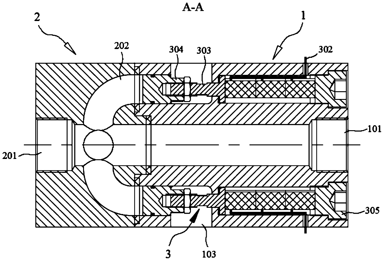
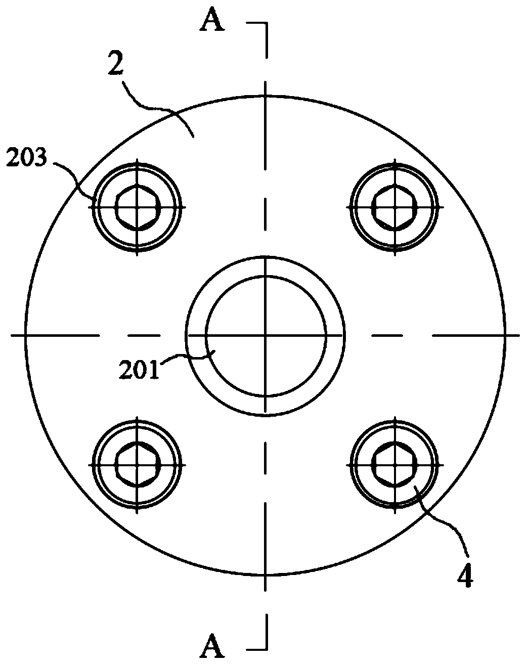
[0034] The overall structure of the active pulsation attenuation device in the preferred embodiment of the present invention is as follows figure 1 As shown in , where, it is not difficult to see from the diagram that the active pulsation damping device includes a first base 1 and a second base 2 that can be closely matched coaxially.

[0035] Specifically, the first substrate 1 in the ...


PUM


Abstract

The invention discloses an active pulsation attenuation device, and belongs to the field of vibration damping and noise reduction equipment. By correspondingly arranging a first base body and a secondbase body which are provided with flow channels and corresponding holes and can be hermetically connected with each other and at least one actuating unit which is arranged corresponding to the two base bodies, secondary pulsation can be correspondingly generated in liquid fluid in the flow channels of the two base bodies through control of the actuating unit, and the secondary pulsation and the primary pulsation generated in the liquid fluid transmission process are superposed and offset so as to realize vibration damping and noise reduction in the liquid fluid transmission process. The active pulsation attenuation device is simple in structure, convenient to install and connect, and capable of effectively realizing vibration reduction and noise reduction in the transmission process of the liquid fluid in a pipe and ensuring the accuracy and stability of the liquid fluid transmission; moreover, the controllable states of the active pulsation attenuation device are diversified, the active pulsation attenuation device can be effectively applied to vibration reduction and noise reduction of the liquid fluid in the pipe under different flow states, the application range is wide, the application prospect is good, and the popularization value is high.

Description

technical field [0001] The invention belongs to the field of vibration and noise reduction equipment, and in particular relates to an active pulsation attenuation device that can control the pulsation noise of pipeline liquid. Background technique [0002] In the process of transmitting mass flow, momentum flow or energy flow, the liquid pipeline system often produces fluid pulsation noise, which may cause vibrations throughout the pipeline, affect the normal use of the liquid pipeline system, and even cause damage to the liquid pipeline system. In order to solve or reduce the fluid pulsation noise in the application process of the liquid pipeline system, it is common practice to set corresponding pulsation attenuators on the liquid pipeline system. [0003] According to the difference in the working principle of the pulsation attenuator, it can be divided into active pulsation attenuator and passive pulsation attenuator. Among them, the passive pulsation attenuator is wide...

Claims


Application Information

Patent Timeline
Patent Type & Authority Applications(China)
IPC IPC(8): F16L55/045
CPCF16L55/045
Inventor 徐荣武赵佳锡廖健陈宗斌梁云栋
Owner NAVAL UNIV OF ENG PLA
Learn More