
Sheet conveying mechanism and image forming device

A conveying mechanism and paper technology, which are applied to the electric recording process applying charge pattern, the equipment, transportation and packaging of the electric recording process applying charge pattern, etc., to shorten the paper path, save space, and improve stability.

Inactive Publication Date: 2019-07-02
KONICA MINOLTA TECH DEV WUXI
View PDF12 Cites 0 Cited by
  • Summary
  • Abstract
  • Description
  • Claims
  • Application Information

AI Technical Summary

Problems solved by technology

[0006] It can be seen that in the existing structure, there is room for improvement in terms of reducing scratches and shortening the paper path.

Method used


Image

  • Sheet conveying mechanism and image forming device
  • Sheet conveying mechanism and image forming device
  • Sheet conveying mechanism and image forming device

Examples


no. 1 approach

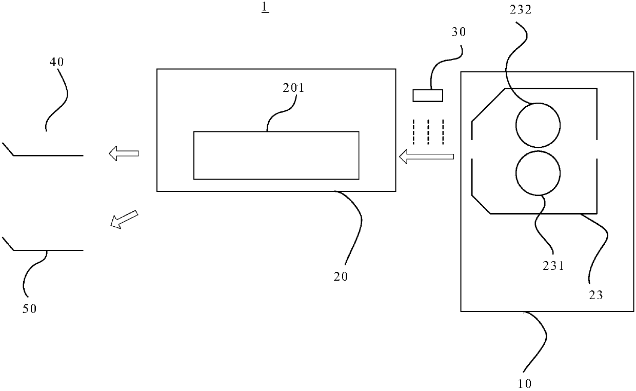
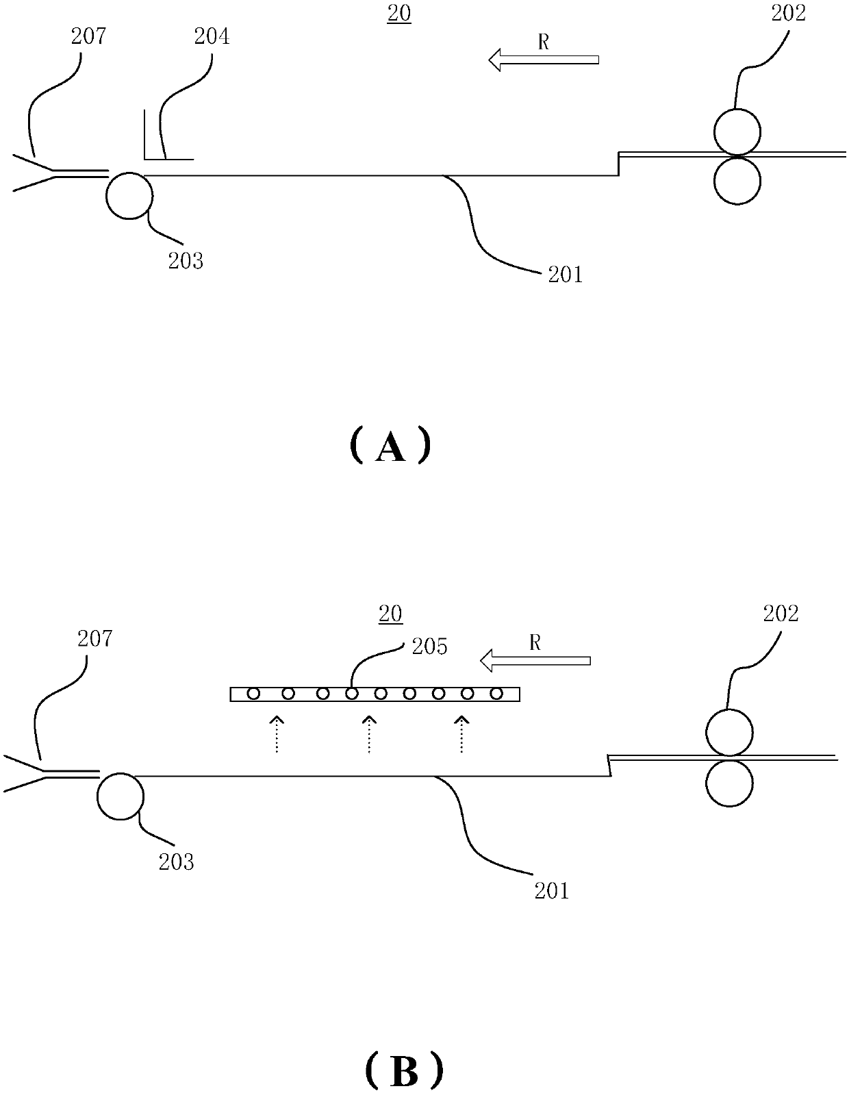
[0069] Such as image 3 As shown, the paper conveying mechanism 20 roughly includes a paper carrying unit 202, a paper temporary storage unit 201, a paper carrying unit 203, and a track switching unit 207.

[0070] The paper carry-in unit 202 is, for example, a pair of carry-in roller pairs, which are provided on the paper transport path and are provided on the downstream side of the transport direction R of the detection unit 30 for transporting in the transport direction R and forming an image in the image forming unit 10 And the paper detected by the detecting unit 30.

[0071] The paper temporary storage unit 201 is, for example, a paper storage tray, which is provided on the downstream side of the paper carry-in unit 202 in the transport direction R, and is used to temporarily store the paper carried in by the paper carry-in unit 202 within a predetermined time. The paper temporary storage unit 201 has a horizontal surface, the paper is stored on the horizontal surface, and th...

no. 2 approach

[0093] Such as Image 6 As shown, the paper transport mechanism 20a of the second embodiment of the present invention roughly includes a paper loading unit 202a, paper temporary storage units 201a, 201b, paper output units 203a, 203b, 203c, 203d, and a switching claw 206, omitting the first The movable pressing piece or paper suction part in the embodiment.

[0094] The paper carry-in unit 202a is, for example, a pair of carry-in rollers, which are arranged on the paper conveying path and are arranged on the downstream side of the conveying direction R of the detection unit 30 for conveying in the conveying direction R the image formed in the image forming unit 10 And the paper detected by the detecting unit 30.

[0095] The paper temporary storage units 201a and 201b are composed of two upper and lower passages, namely, an upper passage 201a and a lower passage 201b. The upper passage 201a and the lower passage 201b are arranged parallel to each other and symmetrically on the down...


PUM


Abstract

The invention relates to a sheet conveying mechanism and an image forming device. The sheet conveying mechanism is provided with a sheet conveying-in unit, a sheet temporary storage unit, a sheet conveying-out unit and a track switching unit, wherein the sheet conveying-in unit is used for conveying sheets which form images in an image forming unit in, and the sheet temporary storage unit is usedfor temporarily storing the sheets conveyed-in by the sheet conveying-in unit within the required time; and the sheet conveying-out unit is used for conveying the sheets stored in the sheet temporarystorage unit out, and the track switching unit is used for switching tracks according to a detection result of a detection unit for detecting the images on the sheets, so that the sheets are conveyedto a first discharge part or a second discharge part.

Description

Technical field [0001] The present invention relates to a paper conveying mechanism and an image forming apparatus, and more particularly to a paper conveying mechanism and an image forming apparatus capable of reducing scratches and shortening the paper path. Background technique [0002] An ICCU (Image Calibration Control Unit) is known, which is used to detect whether the printed image has defects. A paper conveying mechanism is provided on the downstream side of the ICCU in the conveying direction. The paper conveying mechanism cooperates with the ICCU's detection results to send the papers without problems to the downstream in the conveying direction and discharge the problematic papers to the defective paper discharge tray. [0003] Since the ICCU scans the image, it takes time to analyze the image, so if the paper only passes through the straight path on the downstream side of the ICCU conveying direction, the paper will enter the downstream before the analysis is completed,...

Claims


Application Information

Patent Timeline
Patent Type & Authority Applications(China)
IPC IPC(8): B65H3/06G03G15/00
CPCB65H3/063B65H2701/1131G03G15/6529
Inventor 周佳莹
Owner KONICA MINOLTA TECH DEV WUXI
Learn More