An automatic detection method of ultrasonic c-scanning based on industrial robot

An industrial robot, automatic detection technology, used in the analysis of solids using sonic/ultrasonic/infrasonic waves, material analysis using sonic/ultrasonic/infrasonic waves, instruments, etc. Frequent pose adjustment and other problems, to achieve the effect of simplifying the motion path, high detection efficiency, and improving detection accuracy

Active Publication Date: 2021-07-30
CHINA WEAPON SCI ACADEMY NINGBO BRANCH
View PDF6 Cites 0 Cited by
  • Summary
  • Abstract
  • Description
  • Claims
  • Application Information

AI Technical Summary

Problems solved by technology

In the Zigzag circumferential step-by-step scanning method, the industrial robot, as the main movement in the scanning process, carries the probe and moves along the axial direction of the workpiece. Each scan, the workpiece steps a certain angle along the circumferential direction until the workpiece turns 360° and completes. The overall full-coverage C-scan has slow scanning speed and low efficiency, and the posture adjustment of the ultrasonic transducer is too frequent, and when planning the motion path, it is necessary to discrete countless trajectory points to ensure the tracking accuracy of the surface; while in the spiral scanning method, The ultrasonic transducer moves along the direction of the workpiece busbar, and the workpiece rotates continuously. During the scanning process, the ultrasonic transducer only needs to move once in one direction, which can eliminate the step error in the circumferential direction. It is fast, efficient, and can realize continuous scanning. , but the implementation of its imaging algorithm is relatively complicated, and it is easy to cause missed detection when the ultrasonic transducer moves too fast

Method used


Image

  • An automatic detection method of ultrasonic c-scanning based on industrial robot
  • An automatic detection method of ultrasonic c-scanning based on industrial robot
  • An automatic detection method of ultrasonic c-scanning based on industrial robot

Examples


Embodiment Construction

[0042] The present invention will be further described in detail below in conjunction with the accompanying drawings and embodiments.

[0043] A kind of ultrasonic C-scan automatic detection method based on industrial robot, comprises the following steps:

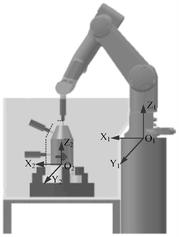
[0044] Step S1. In order to realize accurate path planning based on the CAD model of the workpiece, and facilitate the accurate correspondence between the ultrasonic signal and the spatial position of the C-scan 3D imaging model during the scanning process, it is necessary to use a special teaching pendant for industrial robots or other auxiliary methods to define the reference of the detection system Coordinate System. Place the workpiece to be measured at the center of the turntable, teach the world coordinate system and the reference coordinate system, as follows figure 1 As shown, the world coordinate system is fixed on the base of the industrial robot manipulator and fixed with the installation of the manipulator. The...


PUM


Abstract

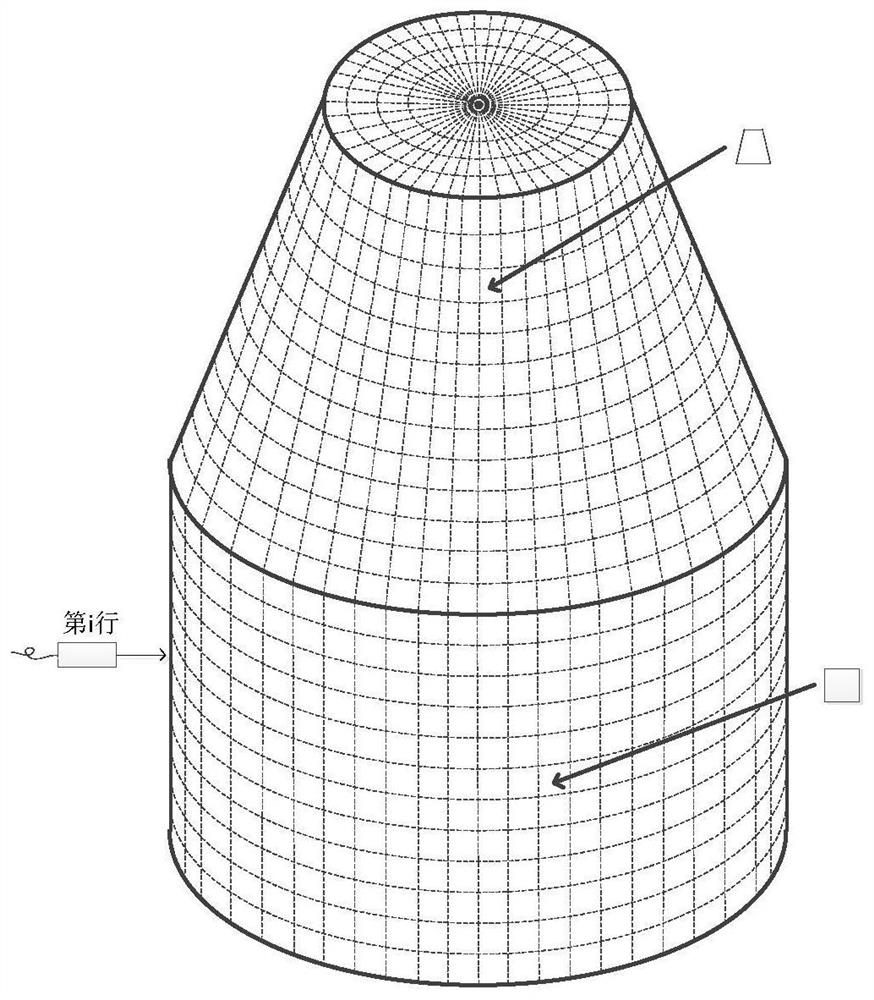
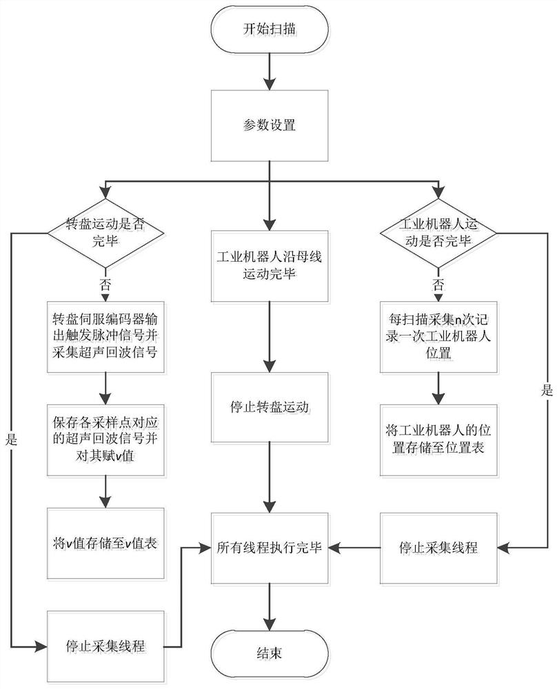
An ultrasonic C-scan automatic detection method, comprising S1, placing a workpiece at the center of a turntable, and teaching a world coordinate system and a reference coordinate system; S2, establishing a three-dimensional imaging model according to the actual size of the workpiece, and dividing sampling points; S3, Obtain the coordinate values ​​of the key points on the bus of the imaging model in the reference coordinate system, and calculate the position value of the industrial robot at the key points; S4, the turntable drives the workpiece to rotate, and the pulse signal is provided by the turntable servo encoder as an ultrasonic transceiver and The external trigger source of the data acquisition card, the industrial robot triggers and collects the workpiece according to each sampling point and the ultrasonic echo signal, so that the ultrasonic echo signal of each sampling point corresponds to the spatial position of the imaging model; S5, data processing , and through the color palette, the feature values ​​of different sampling points correspond to different color values ​​and are mapped to the C-scan image. The detection method greatly simplifies the motion path of the industrial robot and ensures high detection efficiency and detection accuracy.

Description

technical field [0001] The invention relates to the technical field of ultrasonic scanning detection, in particular to an automatic ultrasonic C-scan detection method based on an industrial robot. Background technique [0002] Defects in the manufacturing process of the workpiece will seriously reduce the safety and reliability of its application. Therefore, non-destructive testing must be used in high-end manufacturing to ensure the production quality of these key components. The digital, graphic and intelligent detection methods of ultrasonic C-scan automatic detection technology can intuitively reproduce the size and shape of the internal defects of the workpiece, and realize the qualitative, positioning and quantitative detection of defects, which can be especially applied to missile warhead components, engine casings, etc. Rotary workpieces with complex profiles. [0003] In the process of ultrasonic C-scan automatic detection, there is a high requirement on whether th...

Claims


Application Information

Patent Timeline
Patent Type & Authority Patents(China)
IPC IPC(8): G01N29/06G01N29/22G01N29/275
Inventor 张荣繁李雄兵李红伟郭智敏乔日东郑颖左欣付康唐盛明李岩
Owner CHINA WEAPON SCI ACADEMY NINGBO BRANCH
Why Eureka
Try Eureka