Pneumatic capillary tube clamping device

A technology of clamping device and capillary tube, which is applied in the direction of measuring device, instrument, liquid/fluid solid measurement, etc., can solve the problems of low efficiency, cumbersome loading and unloading, etc., and achieve the effect of efficient operation, labor liberation, and easy processing

Pending Publication Date: 2019-06-28
OCEANOGRAPHIC INSTR RES INST SHANDONG ACAD OF SCI
View PDF0 Cites 0 Cited by
  • Summary
  • Abstract
  • Description
  • Claims
  • Application Information

AI Technical Summary

Problems solved by technology

Each capillary needs to install and disassemble the locking device, which is cumbersome and inefficient

Method used


Image

  • Pneumatic capillary tube clamping device
  • Pneumatic capillary tube clamping device
  • Pneumatic capillary tube clamping device

Examples


Embodiment Construction

[0024] The present invention will be further described below in conjunction with the accompanying drawings and specific embodiments.

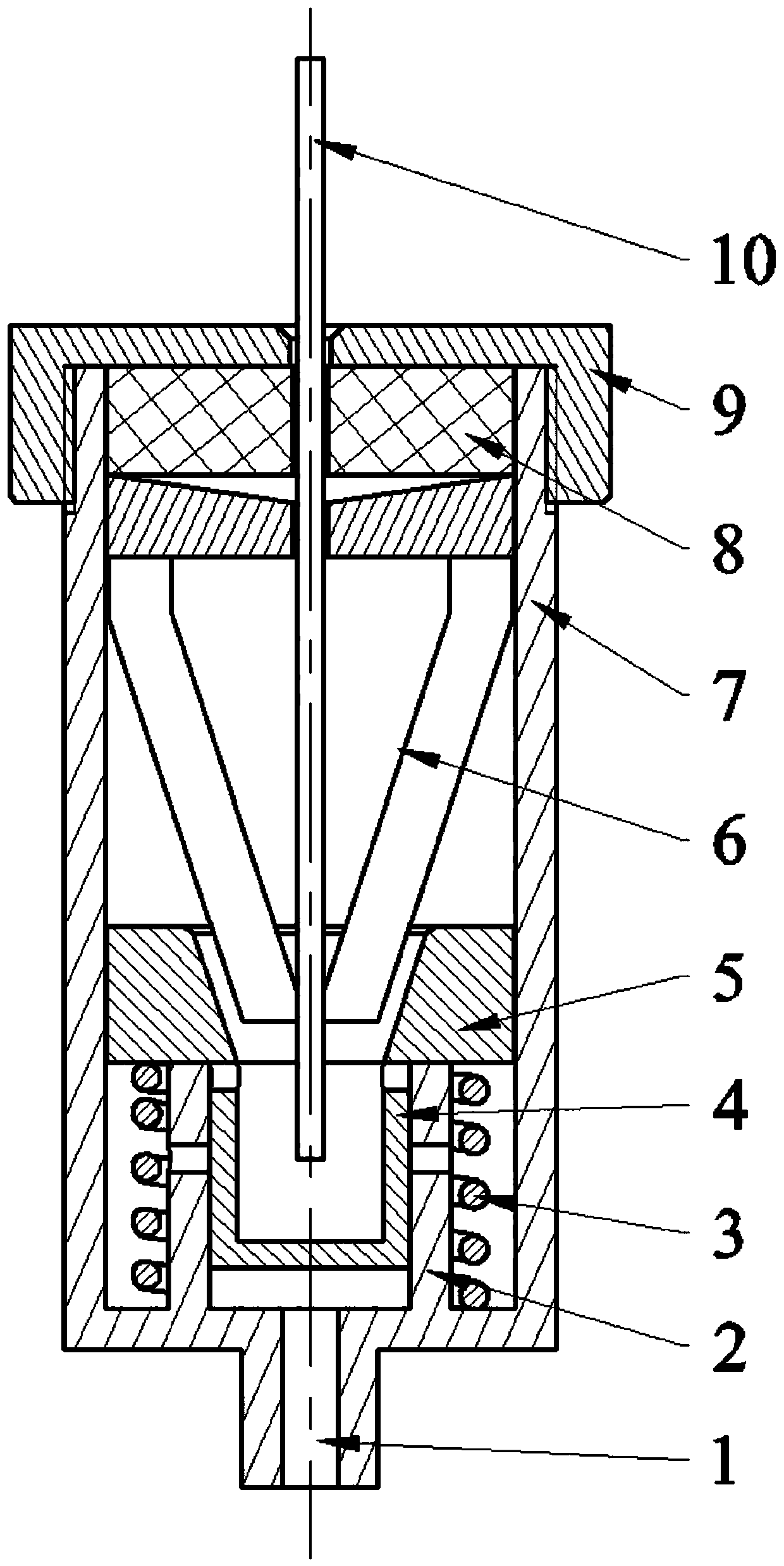
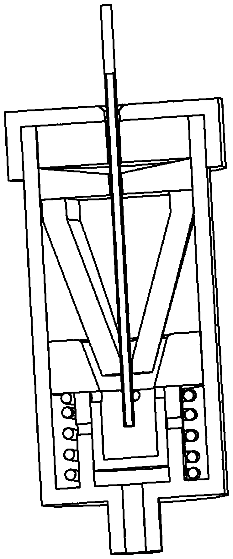
[0025] like Figure 1-2 As shown, a pneumatic capillary clamping device includes a cylinder 7 , a piston 4 , a cylinder head 9 , a spring 3 , a clamping seal 6 and a rubber ring 8 .

[0026] The cylinder barrel 7 is a cylindrical structure, and one end has an external thread to cooperate with the internal thread of the cylinder head 9 to lock; the other end is an air inlet 1, which communicates with a compressed air source. The inner air inlet end of the cylinder 7 is provided with a cylinder 2 communicated with the air inlet 1, the cylinder 2 is tubular, the bottom of the cylinder 2 is integrated with the bottom of the cylinder 7, and the side wall of the cylinder 2 is provided with at least one through hole.

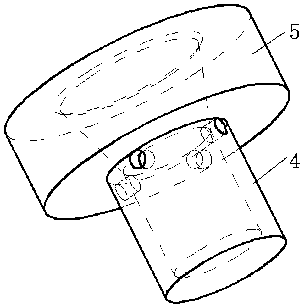
[0027] The piston 4 is installed in the cylinder 2. The outer diameter of the piston 4 is matched with the inner diameter of the cyli...


PUM


Abstract

The invention discloses a pneumatic capillary tube clamping device. The pneumatic capillary tube clamping device comprises a cylinder barrel, a piston, a cylinder cover, a spring, a clamp sealing element and a rubber ring, wherein one end of the cylinder barrel is locked with the cylinder cover in a fit manner, the other end is an air inlet communicated with a compressed air source, a cylinder communicated with the air inlet is arranged at the air inlet end in the cylinder barrel, the piston is mounted in the cylinder, a locking ring is arranged at the top of the piston, a taper hole is formedin the center of the locking ring and communicated with a piston cavity, the locking ring is connected with the bottom of the cylinder barrel through a spring, and the spring is in a stretched state;one end of the clamp sealing element is a clamp end, the clamp end is in telescopic fit with the locking ring, the other end of the clamp sealing element is a sealing end, a rubber ring is arranged between the sealing end and the cylinder cover, and a capillary tube penetrates through the cylinder cover, the rubber ring and the clamp sealing element and extends into the piston. According to the pneumatic capillary tube clamping device, two processes of connecting the air source to lock the capillary tube automatically and disconnecting air to release the capillary tube automatically are realized, labors are liberated, test time is shortened, degree of automation of a test is increased, and a test technology is simplified.

Description

technical field [0001] The invention belongs to the technical field of flow testing, and relates to capillary flow testing equipment, in particular to a pneumatic capillary clamping device. Background technique [0002] In the prior art, the testing process of the capillary flow testing equipment is: inserting the capillary; installing the locking device; connecting the test gas; testing; disconnecting the test gas; disassembling the locking device; pulling out the capillary. Each capillary requires installation and disassembly of a locking device, which is cumbersome and inefficient. Therefore, changing manual locking to automatic locking will be of great significance for improving the degree of automation and streamlining the testing process. Contents of the invention [0003] Aiming at the deficiencies in the prior art, the invention provides a pneumatic clamping device for capillary flow testing equipment with simple structure and high operating efficiency. As long a...

Claims


Application Information

Patent Timeline
IPC IPC(8): G01F15/00
Inventor 高骋飞郑轶王亚洲卢涛杨群毛宇峰李腾刘海林
Owner OCEANOGRAPHIC INSTR RES INST SHANDONG ACAD OF SCI
Why Eureka
Try Eureka