Underground sewage pipeline health detection device and installation method of detection device

A technology for health detection and sewage pipelines, applied in pipeline systems, mechanical equipment, gas/liquid distribution and storage, etc., can solve the problems of fiber waste, long fiber length, etc., to reduce the length of use, save costs, and facilitate installation.

Active Publication Date: 2019-06-28
南京市市政设计研究院有限责任公司
View PDF7 Cites 2 Cited by
  • Summary
  • Abstract
  • Description
  • Claims
  • Application Information

AI Technical Summary

Problems solved by technology

[0004] When laying, in the prior art, the optical fiber is laid in the pipe in a spiral shape, which can ensure that the optical fiber completely covers the inner wall of the pipe. However, if the optical fiber is arranged in a spiral shape, the required length of the optical fiber will be very long, which will easily cause waste of optical fiber

Method used


Image

  • Underground sewage pipeline health detection device and installation method of detection device
  • Underground sewage pipeline health detection device and installation method of detection device
  • Underground sewage pipeline health detection device and installation method of detection device

Examples


Embodiment 1

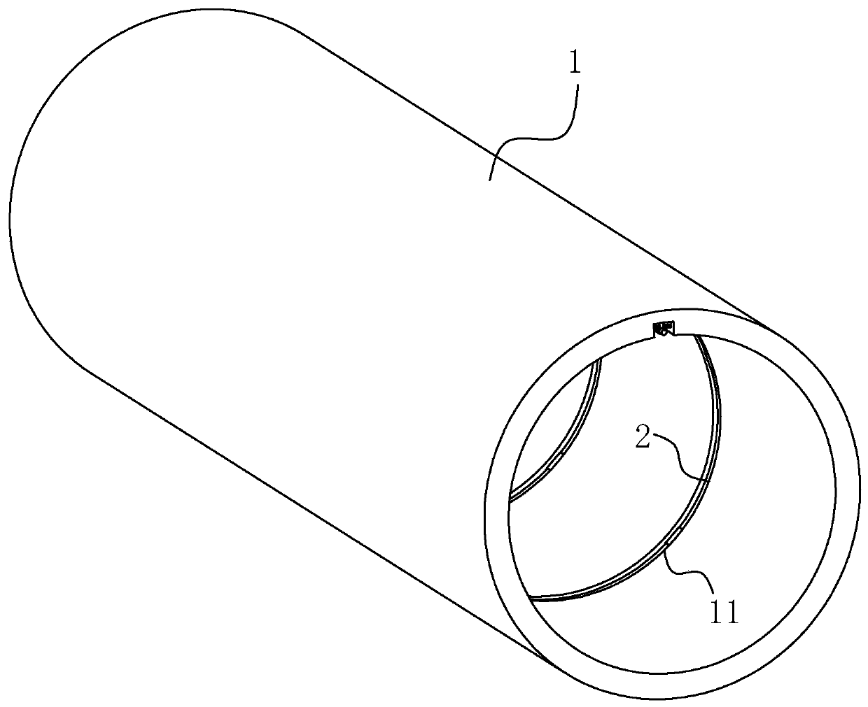
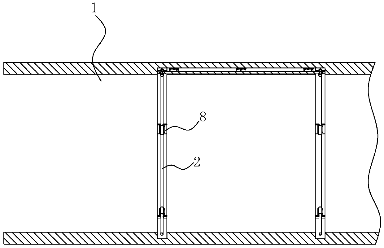
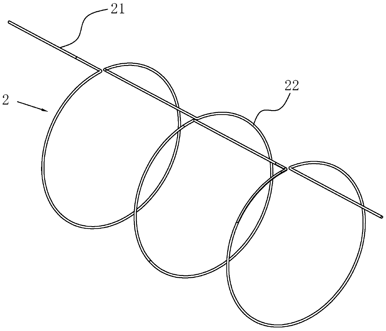
[0044] refer to figure 1 as well as figure 2 , is a health detection device for an underground sewage pipeline 1 disclosed by the present invention, comprising a detection optical cable 2 laid on the pipeline 1 along the length direction of the pipeline 1, referring to image 3The detection optical cable 2 is composed of an axial section 21 and a circumferential section 22 at intervals. The interval between the axial section 21 and the circumferential section 22 is determined according to the inner diameter of the pipe 1. If the inner diameter of the pipe 1 is small, all of them are arranged in a straight line. On the pipeline 1, there is a fixing device for fixing the detection optical cable 2 on the pipeline 1. During detection, the axial section 21 detects the data in the axial direction of the pipeline 1, and the circumferential section 22 detects the data in the circumferential direction. When laying, the straight section and the circumferential section 22 are combined ...

Embodiment 2

[0052] A method for installing a detection device, comprising the following steps:

[0053] Step S1: Line setting, first use the ink cartridge to draw the line and put the line on the surface of the pipeline 1 to draw the planned laying line. The line is kept straight along the axial direction of the pipeline 1, and the line is guaranteed to be circular along the circumferential direction. Use ink cartridges The way of drawing the line can roughly plan the direction of the detection optical cable 2 and improve the accuracy in the laying process.

[0054] In step S1, for the pipeline 1 laid by the open cut method, the detection optical cable 2 is arranged on the outer wall of the pipeline 1; for the pipeline 1 laid by the underground excavation method, the detection optical cable 2 is arranged on the inner wall of the pipeline 1, according to specific construction conditions Selecting the laying position of the detection optical cable 2 is not only convenient for operation, but...


PUM


Abstract

The invention relates to an underground sewage pipeline health detection device and an installation method of the detection device. The underground sewage pipeline health detection device comprises adetection optical cable laid on a pipeline in the length direction of the pipeline, the detection optical cable is composed of axial sections and annular sections at intervals, the pipeline is provided with a fixing device for fixing a detection optical cable on the pipeline, and the detection optical cable is fixed on the pipeline through the fixing device; and during detection, the axial sections are used for detecting data in the axis direction of the pipeline, and the annular sections are used for detecting the data in the annular section. The detection optical cable can be combined with each other through straight line sections and the annular sections during laying, it is guaranteed that the detection optical cable can completely cover the pipeline, the pipeline can be accurately detected, the use length of the detection optical cable during laying can be saved as well, waste is avoided, meanwhile, the laying difficulty is lowered, and the construction cost is reduced.

Description

technical field [0001] The invention relates to the technical field of pipeline health detection, in particular to an underground sewage pipeline health detection device and an installation method of the detection device. Background technique [0002] Pipeline transportation has the characteristics of safety, convenience and economy, but pipeline failure accidents may occur due to external disturbance, corrosion, pipe material and construction quality and other reasons. In order to ensure the safety of pipeline transportation, it is necessary to monitor the health status of the pipeline in real time to deal with the serious consequences caused by pipeline corrosion and stress failure. The distributed optical fiber sensing technology developed in recent years has become a new method for pipeline health monitoring at home and abroad due to its advantages of long distance, high sensitivity, passive corrosion resistance and online detection, and has developed rapidly. [0003] ...

Claims


Application Information

Patent Timeline
IPC IPC(8): F17D5/00F17D1/08
Inventor 张树俊高磊唐玉宏彭军方伟
Owner 南京市市政设计研究院有限责任公司
Why Eureka
Try Eureka