
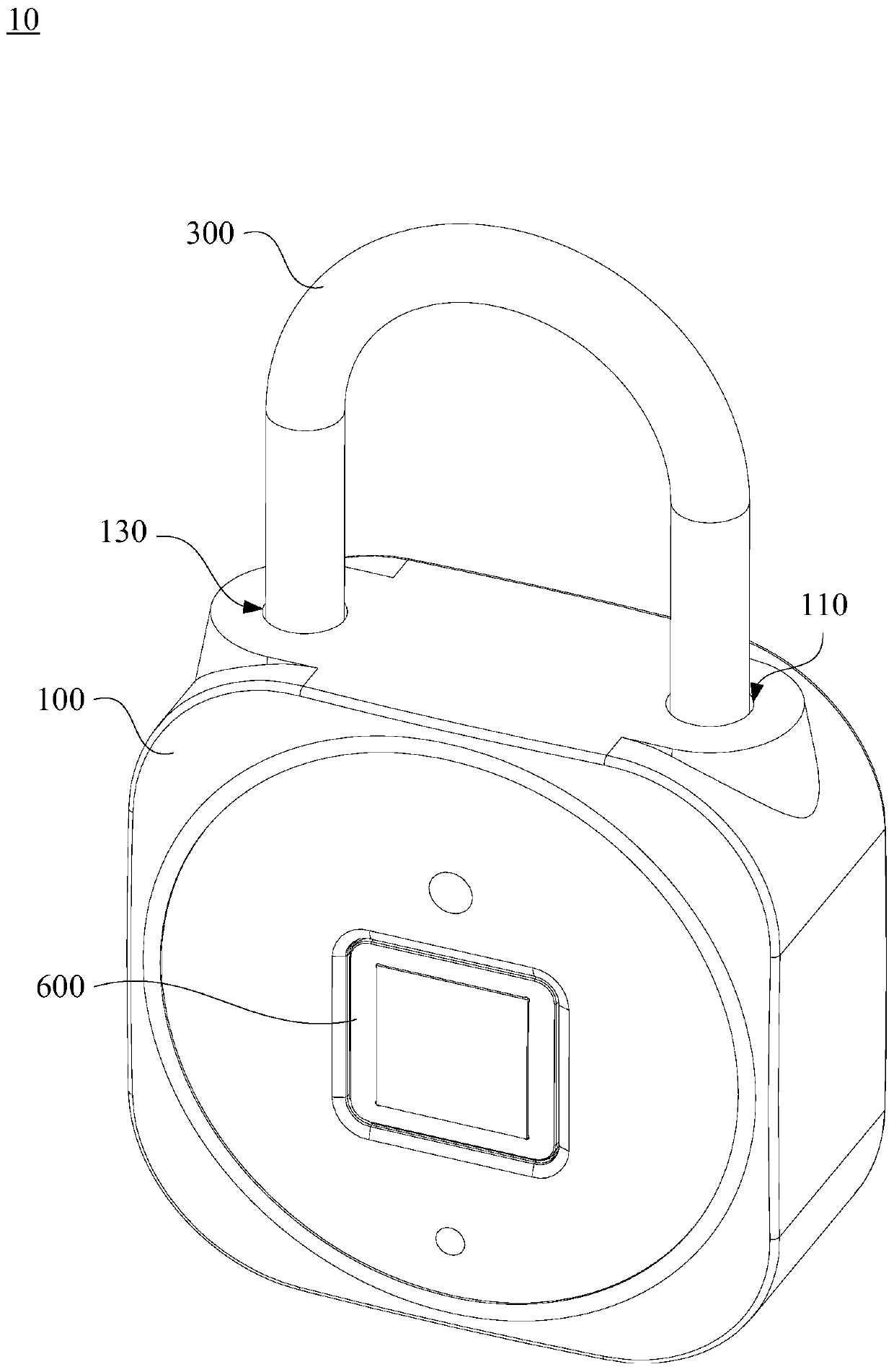
Electronic lock

An electronic lock and lock beam technology, applied in the field of electronic locks, can solve problems such as poor security of electronic locks, and achieve the effect of improving security and reliably maintaining the locked state.

Pending Publication Date: 2019-06-28
HUIZHOU BOSHIJIE TECH CO LTD
View PDF0 Cites 1 Cited by
  • Summary
  • Abstract
  • Description
  • Claims
  • Application Information

AI Technical Summary

Problems solved by technology

[0004] Based on this, it is necessary to provide an electronic lock for the problem of poor security of the electronic lock

Method used


Image

  • Electronic lock
  • Electronic lock
  • Electronic lock

Examples


Embodiment Construction

[0027] In order to facilitate the understanding of the present application, the electronic lock will be described more fully below with reference to the relevant drawings. A preferred embodiment of the electronic lock is shown in the accompanying drawings. However, electronic locks can be implemented in many different forms and are not limited to the embodiments described herein. On the contrary, the purpose of providing these embodiments is to make the disclosed content of the electronic lock more thorough and comprehensive.

[0028] It should be noted that when an element is referred to as being “fixed” to another element, it can be directly on the other element or there can also be an intervening element. When an element is referred to as being "connected to" another element, it can be directly connected to the other element or intervening elements may also be present. The terms "vertical," "horizontal," "left," "right," and similar expressions are used herein for purpose...


PUM


Abstract

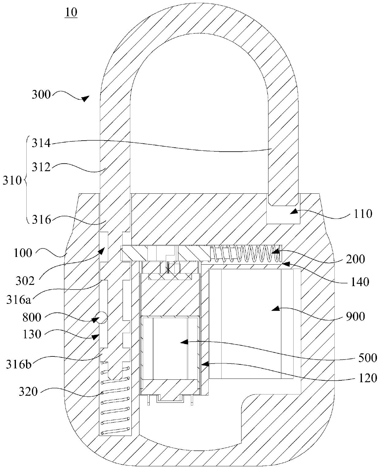
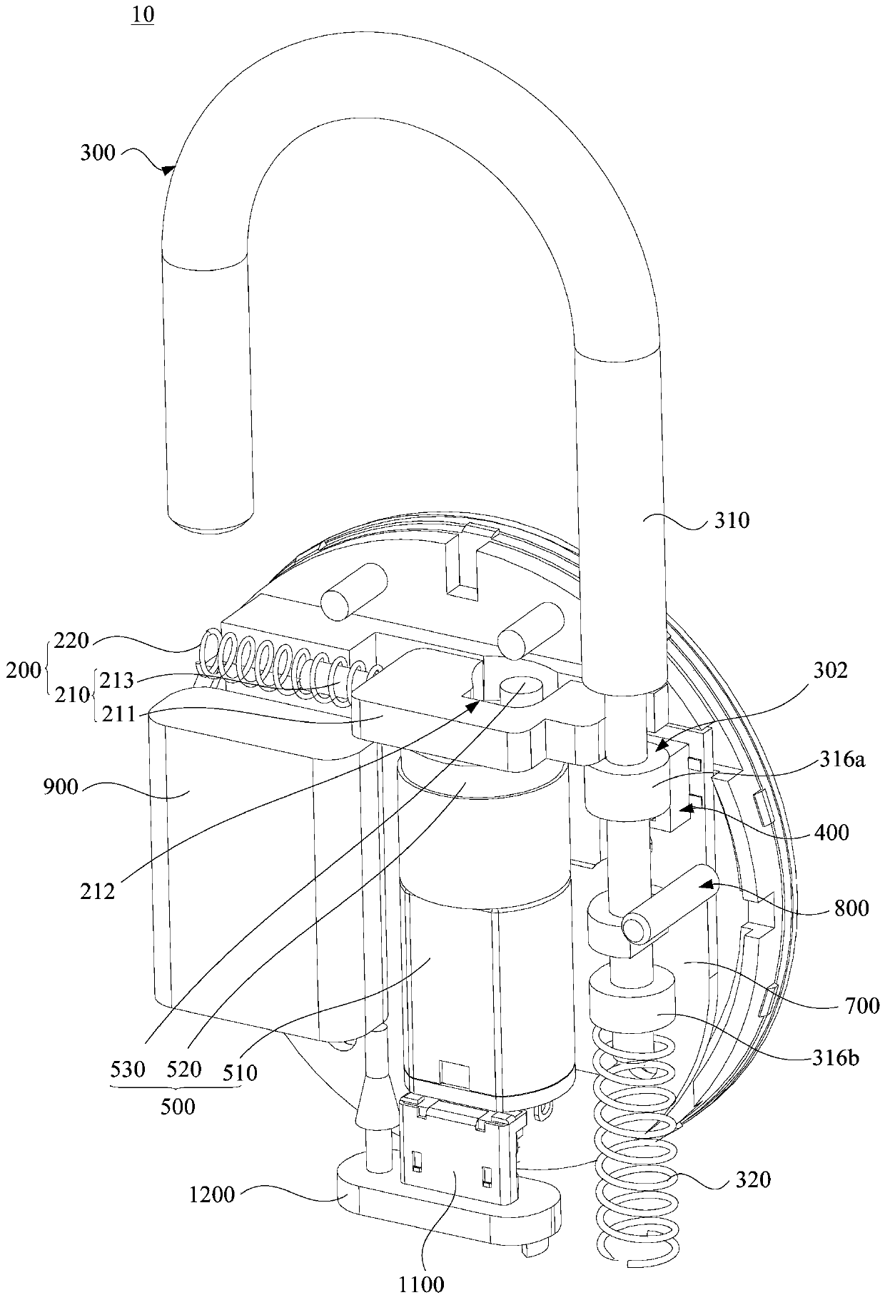
The invention relates to an electronic lock. The above electronic lock comprises a lock body, a lock pin assembly and a lock beam assembly. The lock pin assembly and the lock beam assembly are arranged on the lock body in a sliding manner, the sliding direction of the lock pin assembly and the sliding direction of the lock beam assembly are intersected, and a limiting groove is formed in the lockbeam assembly. The electronic lock further comprises a switch assembly and a driving mechanism, and the switch assembly is arranged on the lock body. The driving mechanism is electrically connected with the switch assembly, and the driving mechanism is used for driving the lock pin assembly to be inserted into the limiting groove when the lock beam assembly is connected to the switch assembly in an abutting manner to make the switch assembly pressed. Due to the fact that the sliding direction of the lock pin assembly and the sliding direction of the lock beam assembly are intersected, the lockpin assembly can be reliably positioned on the lock beam assembly, it is ensured that the lock beam assembly is static relative to the lock body, locking of the electronic lock is achieved, it is avoided that the lock beam assembly slides relative to the lock body when the electronic lock is subjected to external inertia knocking, the problem that the electronic lock is accidentally opened is solved, and safety of the electronic lock is improved.

Description

technical field [0001] The present application relates to the technical field of locks, in particular to an electronic lock. Background technique [0002] An electronic lock is an electronic product that controls the operation of a circuit or a chip (access control system) through a password input, thereby controlling the closing of a mechanical switch and completing the task of unlocking or locking. Electronic locks are widely used in places such as hotels, guesthouses, apartments or villas. The electronic lock has the anti-theft alarm function in the field of security technology prevention, and overcomes the shortcomings of the mechanical combination lock with less passwords and poor security performance. [0003] After the traditional electronic lock is locked, the lock pin can still move relative to the lock body. When the electronic lock is knocked by the inertia of the outside, the lock pin moves relative to the lock body, so that the lock beam is accidentally opened...

Claims


Application Information

Patent Timeline
Patent Type & Authority Applications(China)
IPC IPC(8): E05B49/00E05B17/20E05B15/00
Inventor 周小强赵建华李小民吴东南李腾达
Owner HUIZHOU BOSHIJIE TECH CO LTD
Learn More