
Heat meter device with rotating device

A heat meter and equipment technology, applied in the field of heat meters, can solve problems such as increased construction costs, difficulty in disassembly, cumbersome manual movement, etc., and achieve the effect of reducing construction costs and reasonable structure

Inactive Publication Date: 2019-06-25
XIAN TRIONES DIGITAL INFORMATION
View PDF0 Cites 0 Cited by
  • Summary
  • Abstract
  • Description
  • Claims
  • Application Information

AI Technical Summary

Problems solved by technology

[0002] The weight of a high-load heat meter is not small. When the location needs to be changed, manual movement is very cumbersome, and it must be easily achieved by installing a running device such as a ball on the cover of the heat meter.
The structure of the current operating heat meter usually positions the ball on the heat meter through two pairs of screw screws, making it difficult to disassemble. The heat meter can also be turned up, and the ball is positioned on the platform by means of the lead screw and the screw groove. This increases the construction cost

Method used


Image

  • Heat meter device with rotating device
  • Heat meter device with rotating device

Examples


Embodiment Construction

[0014] The present invention will be further described below in conjunction with examples.

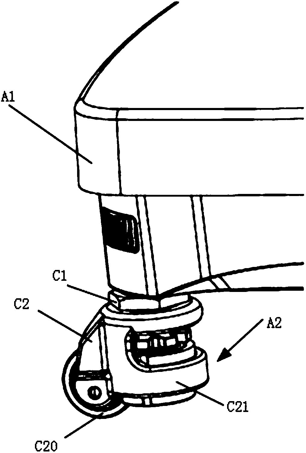
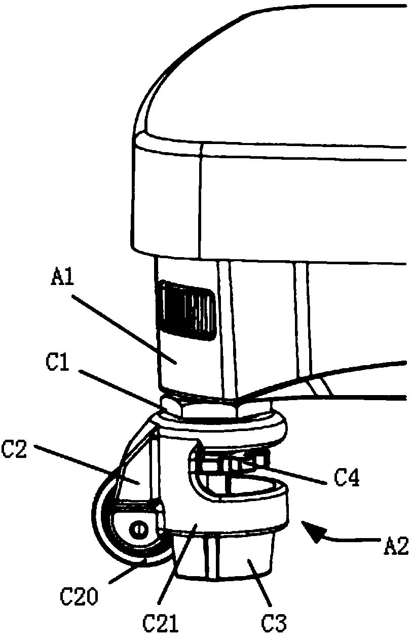
[0015] Such as Figure 1-Figure 2 As shown, the heat meter device with rotating equipment in this embodiment includes the heat meter A1 and the operating equipment A2, the operating equipment A2 is composed of several balls, the structure of the balls can be several profiles, and its rotating section C20 can be ring or ring.

[0016] The ball includes a supporting frame C1 and a hinged section C2. The hinged section C2 is equipped with a rotating section C20 and a clamp C21. The hinged section C2 is connected to the supporting frame C1 and can rotate around a longitudinal centerline in the entire circumferential area.

[0017] The ball also includes a rotating and changing section C4 and a foot plate C3. The rotating and changing section C4 is a ring-shaped disc, which can also be another profile. Rotate in the circumferential area, but not vertically.

[0018] The foot plate C3 is ...


PUM


Abstract

The invention provides a heat meter device with a rotating device. A running device is composed of a plurality of balls. The structure of the balls can be a plurality of contours, and the rotating portion of each ball can be a ring body or an annular body. Each ball comprises a support frame and an articulated section. Each articulated section is provided with a rotating section and a clamp. Eacharticulated section is connected with a support frame and can rotate in a full circumferential area of a longitudinal center line. The disadvantage of increased construction cost in the prior art is effectively avoided.

Description

technical field [0001] The invention relates to the technical field of heat meters, in particular to a heat meter device with rotating equipment. Background technique [0002] The weight of a high-load heat meter is relatively large. When the location needs to be changed, manual movement is very cumbersome, and it must be easier to achieve by installing a running device such as a ball on the cover of the heat meter. The structure of the current operating heat meter usually positions the ball on the heat meter through two pairs of screw screws, making it difficult to disassemble. The heat meter can also be turned up, and the ball is positioned on the platform by means of the lead screw and the screw groove. This increases construction costs. Contents of the invention [0003] In order to solve the above problems, the present invention provides a heat meter device with rotating equipment, which effectively avoids the defect of increasing the construction cost in the prior a...

Claims


Application Information

Patent Timeline
Patent Type & Authority Applications(China)
IPC IPC(8): G01K17/00
Inventor 吴新潮
Owner XIAN TRIONES DIGITAL INFORMATION
Learn More