
Transformer automatic assembly method based on machine vision

A machine vision and automatic assembly technology, applied in the direction of assembly machines, manipulators, program control manipulators, etc., can solve problems such as large labor consumption, low work efficiency, and inability to guarantee product assembly accuracy

Active Publication Date: 2021-05-07
NANJING UNIV OF SCI & TECH
View PDF7 Cites 0 Cited by
  • Summary
  • Abstract
  • Description
  • Claims
  • Application Information

AI Technical Summary

Problems solved by technology

At present, the transformer assembly process in many factories is still done manually, which consumes a lot of labor, and at the same time, the work efficiency is low, and the assembly accuracy of the product cannot be guaranteed.

Method used


Image

  • Transformer automatic assembly method based on machine vision
  • Transformer automatic assembly method based on machine vision
  • Transformer automatic assembly method based on machine vision

Examples


Embodiment Construction

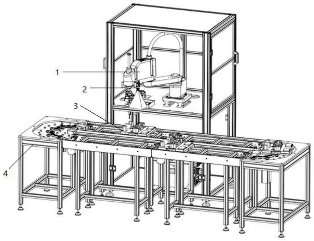
[0019] combine figure 1 , The equipment for automatic transformer assembly of the present invention includes a bracket, a manipulator 1, a camera 2, a material tray 3, and a conveyor 4. The manipulator 1 is set on the support and can rotate in three degrees of freedom, and the camera 2 is set on the manipulator 1 . The material tray 3 is arranged on the conveyor 4 , and the material tray 3 moves together with the conveyor belt of the conveyor 4 . The conveyor 4 is equipped with a photoelectric switch at the working area of ​​the manipulator 1. When the material tray 3 triggers the photoelectric switch, the conveyor belt stops. When the workpiece assembly of a process is completed, the material tray 3 is transferred to the next station.

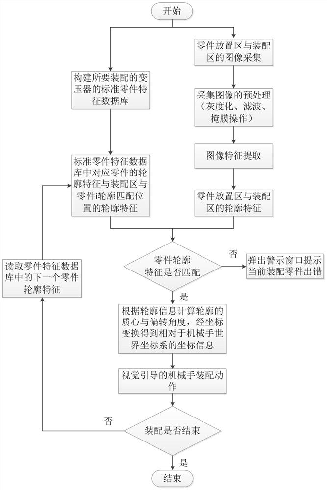
[0020] combine figure 2 , a machine vision-based automatic assembly method for transformers, including building a standard part feature database and assembly of transformers to be assembled.

[0021] The data stored in the standard part fe...


PUM


Abstract

The invention provides an automatic transformer assembly method based on machine vision, which includes constructing a standard part feature database of the transformer to be assembled, collecting images of the part placement area and assembly area, image feature extraction, part matching, obtaining the assembly path of the manipulator, and assembling . The invention uses a camera instead of human eyes to measure the assembly position, which improves the assembly accuracy of the product and reduces labor consumption. This assembly method not only works stably, but also greatly improves the production efficiency and automation of production. It is suitable for large Batch transformer production and assembly process.

Description

technical field [0001] The invention relates to a mechanical automation and machine vision technology, in particular to a machine vision-based automatic transformer assembly method. Background technique [0002] With the rapid development of machine vision technology, flexible assembly has gradually attracted people's attention. The use of vision technology can enable the robot to make independent decisions based on factors such as the surrounding environment and operating conditions, realize dynamic adjustment of the position of the grab point, and quickly adjust the attitude of the parts. Precisely place it in the area to be assembled, etc., so as to improve the stability and production efficiency of product assembly. Nowadays, under the trend of increasing demand for manufacturing products and higher and higher product quality requirements, flexible assembly is widely used in production practice because of its high assembly accuracy, strong stability, and high work effici...

Claims


Application Information

Patent Timeline
Patent Type & Authority Patents(China)
IPC IPC(8): B23P21/00B25J9/16
Inventor 孔令聪顾士晨刘志蔡峰何博侠
Owner NANJING UNIV OF SCI & TECH
Learn More