
A high-voltage narrow pulse modulation circuit

A technology of modulation circuit and narrow pulse, which is applied in the field of high-voltage narrow pulse modulation circuit, can solve problems such as inability to obtain peak power, imperfection, long discharge circuit, etc., achieve reduction of drive loop area and discharge loop area, rational design and Layout structure, the effect of ensuring the conduction speed

Pending Publication Date: 2019-06-21
GUIZHOU AEROSPACE ELECTRONICS TECH
View PDF7 Cites 2 Cited by
  • Summary
  • Abstract
  • Description
  • Claims
  • Application Information

AI Technical Summary

Problems solved by technology

However, the high-voltage drain modulation technology for GaN power devices is still in the initial stage of research, and the corresponding devices and circuit structures are immature and imperfect.
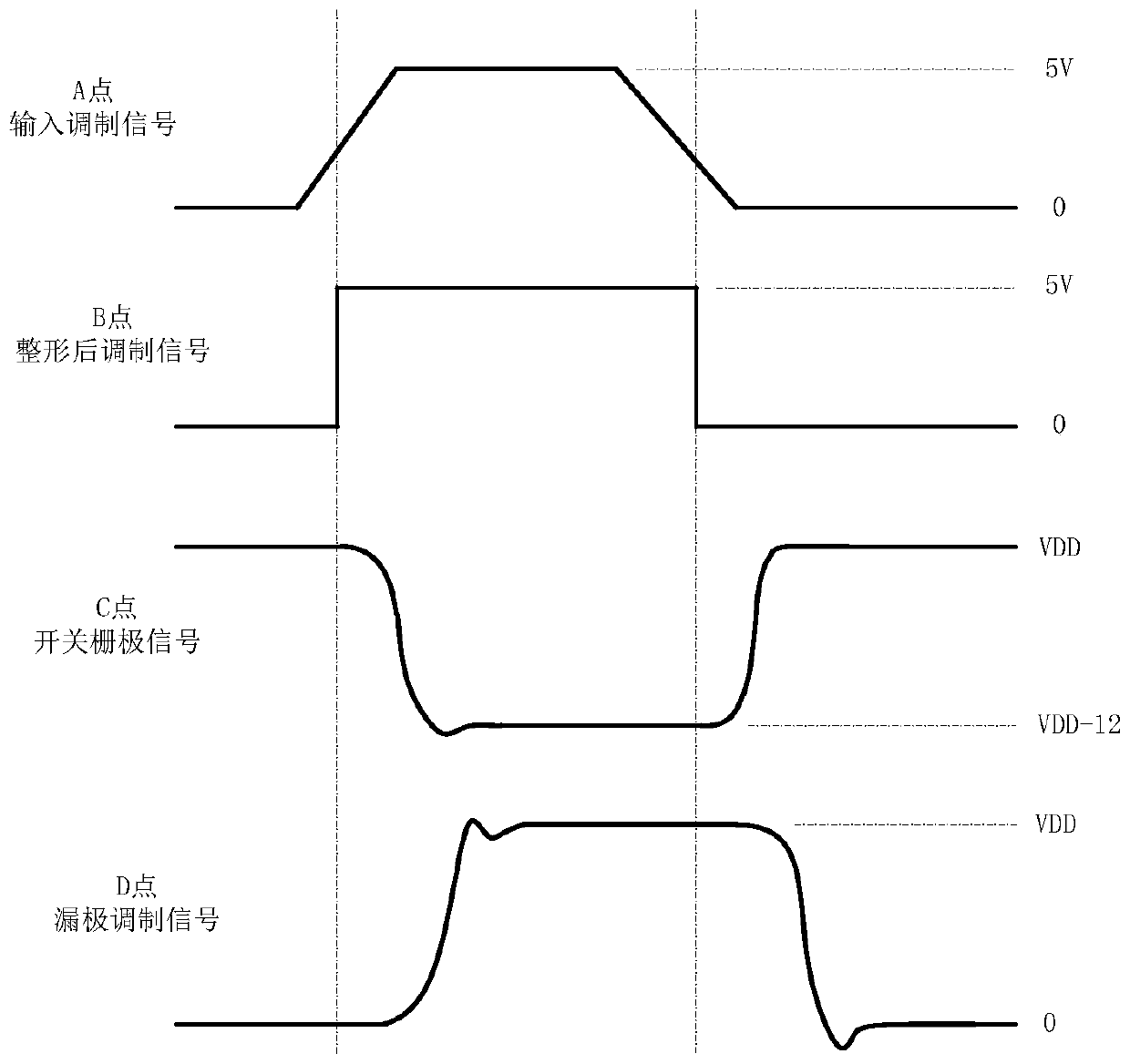
[0004] For example, a GaN power device drain modulation circuit disclosed by the publication number CN104796098A includes a modulation switch gate drive circuit, a modulation switch tube, a voltage divider comparison network, a dead time logic control circuit, a discharge switch tube gate drive circuit, a discharge For switching tubes and power devices, the circuit is drain modulation. Before the input modulation signal enters the debugging switch tube gate drive circuit, due to the influence of factors such as driving capability and printed wiring, the signal has already been deformed and distorted when it reaches the circuit. , so that the rising edge time of the drain modulation signal output by the gate drive circuit of the debugging switch tube is too long. When the circuit structure is designed on the circuit board, there is a long discharge circuit, which will cause the falling edge time of the drain modulation signal to become longer. , using this circuit structure to design the drain modulation circuit, the rising edge time of the drain modulation signal is generally above 60ns, and the falling edge time is generally above 100ns, which will cause the energy consumption of GaN power devices when narrow pulse drain modulation is used. Larger, unable to obtain the required peak power, and at the same time restricting the power device to output higher peak power, which further affects the application of solid-state power amplifiers in radar systems

Method used


Image

  • A high-voltage narrow pulse modulation circuit
  • A high-voltage narrow pulse modulation circuit
  • A high-voltage narrow pulse modulation circuit

Examples


Embodiment Construction

[0018] The technical solution of the present invention is further described below, but the scope of protection is not limited to the description.

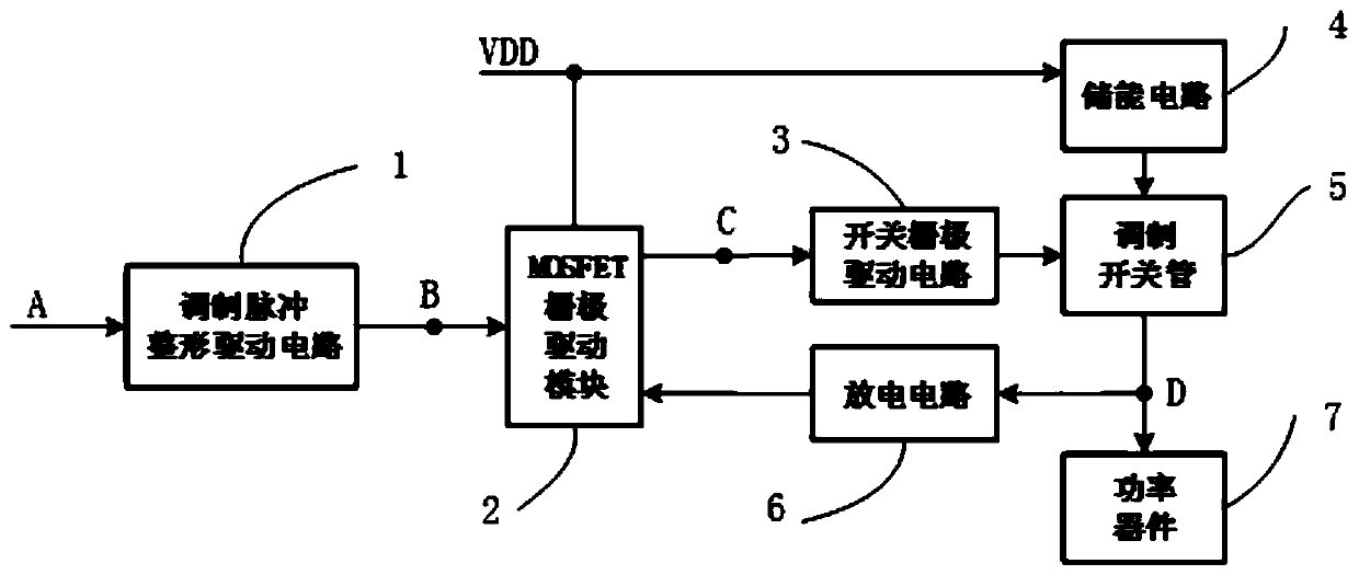
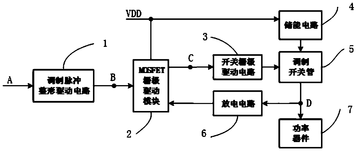
[0019] A high-voltage narrow pulse modulation circuit includes a modulation pulse shaping drive circuit, a MOSFET gate drive module, a switch gate drive circuit, a modulation switch tube, a discharge circuit, an energy storage circuit, and a power device. The modulation pulse shaping drive circuit and the MOSFET The gate drive module is connected, the MOSFET gate drive module is connected with the switch gate drive circuit, the energy storage circuit, the modulation switch tube, and the discharge circuit in sequence to form a closed loop, and the MOSFET gate drive module is connected with the switch gate drive circuit, the modulation switch tube, The power devices are connected sequentially.

[0020] The modulation pulse shaping driving circuit shapes the input signal, and transmits the driving current to the MOSFET gate driving mo...


PUM


Abstract

The invention discloses a high-voltage narrow pulse modulation circuit which comprises a modulation pulse shaping drive circuit,a MOSFET gate drive module, a switch gate drive circuit, a modulation switch tube, a discharging circuit, an energy storage circuit and a power device, the modulation pulse shaping drive circuit is connected with the MOSFET grid drive module, the MOSFET gate drive moduleis connected with the switch gate drive circuit, the energy storage circuit, the modulation switch tube, the discharge circuits are sequentially connected to form a closed loop; the MOSFET gate drivemodule is connected with the switch gate drive circuit; the modulation switch tube, the power devices sequentially. In the invention, the influence of wiring of the printed board on modulation signalwaveform distortion is reduced; the driving capability is improved, the quick response of the gate driving module is ensured, the gate of the modulation switch tube obtains higher instantaneous current, the on-off response time of the modulation switch tube is prolonged, the discharge time of a power device is shortened, and the ringing effect of drain modulation pulse signals is reduced by adopting reasonable energy storage circuit design and layout structure.

Description

technical field [0001] The invention relates to a high voltage narrow pulse modulation circuit. Background technique [0002] With the continuous maturity of GaN power device application technology and manufacturing process, high-power solid-state power amplifiers developed with GaN power devices are more and more widely used in radar systems. At the same time, the corresponding pulse modulation technology and circuits are also constantly developing and improving. At present, the widely used modulation methods include gate modulation and drain modulation, among which the drain modulation has become the preferred modulation method for high-power amplifier modulation circuits because of its strong anti-interference ability and high reliability. [0003] As the output power of solid-state power amplifiers continues to increase, GaN power devices require smaller duty cycles of modulation signals, narrower modulation pulses, and shorter pulse rising and falling times in order to ...

Claims


Application Information

Patent Timeline
IPC IPC(8): H03F1/32H03F3/21H03K17/041
Inventor 杨留邡谭琮龙倩
Owner GUIZHOU AEROSPACE ELECTRONICS TECH
Learn More