
Motor control device, electronic equipment and control method of electronic equipment

A technology for electronic equipment and control devices, applied in motor control, control systems, electrical components, etc., can solve the problems that electronic equipment cannot continue to be used normally, the motor cannot drive the camera, and the resistance of the motor increases, so as to achieve long-term normal use. , to ensure long-term normal use, improve the effect of the user experience

Active Publication Date: 2019-06-21
GUANGDONG OPPO MOBILE TELECOMM CORP LTD
View PDF4 Cites 0 Cited by
  • Summary
  • Abstract
  • Description
  • Claims
  • Application Information

AI Technical Summary

Problems solved by technology

[0002] In the related art, when the motor is in use, most of the driven parts are driven by a transmission mechanism such as a slide rail device. As time increases, due to the aging of the transmission mechanism, the motor cannot realize the normal action of the driven part; for example, In order to achieve a full-screen design, some mobile terminal devices such as smart phones adopt a pop-up camera design, which drives the camera up through a motor, thereby avoiding opening holes in the screen, and then with the increase of use time, the transmission mechanism will age and the motor will run When the resistance increases, the motor cannot drive the camera to rise normally, making the electronic equipment unable to continue to use normally, which affects the user experience

Method used


Image

  • Motor control device, electronic equipment and control method of electronic equipment
  • Motor control device, electronic equipment and control method of electronic equipment
  • Motor control device, electronic equipment and control method of electronic equipment

Examples


Embodiment Construction

[0030] Embodiments of the present application are described in detail below, and examples of the embodiments are shown in the drawings, wherein the same or similar reference numerals denote the same or similar elements or elements having the same or similar functions throughout. The embodiments described below by referring to the figures are exemplary, and are only for explaining the present application, and should not be construed as limiting the present application.

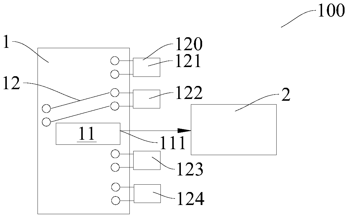
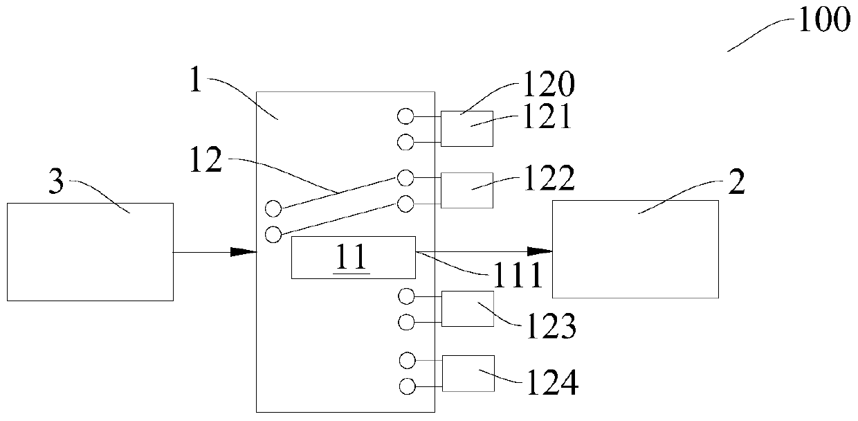
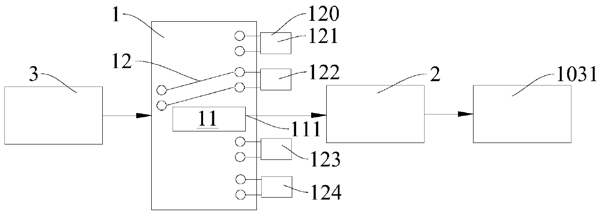
[0031] Refer below Figure 1-Figure 3 The control device 100 of the motor 1031 according to the embodiment of the present application will be described.

[0032] Such as Figure 1-Figure 3 As shown, the control device 100 for a motor 1031 according to the embodiment of the present application includes a switching module 1 and a motor driver 2 .

[0033] The switch module 1 includes a control circuit 11 and a switch 12, the control circuit 11 has an output terminal 111, the switch 12 has a plurality of gears 1...


PUM


Abstract

The invention discloses a motor control device, electronic equipment and a control method of the electronic equipment. The motor control device comprises a switching module and a motor driver, whereinthe switching module comprises a control circuit and a changeover switch, the control circuit is provided with an output end, the changeover switch is provided with a plurality of shifts, a referencevoltage of the output end can be switched by the changeover switch, the motor driver is connected with an output end of the switch module, and the motor driver suitably connected with the motor so asto load an output current of the motor driver to a motor. According to the motor control device, a driving force of the motor can be adjusted, so that the driving force of the motor and motor runningare matched by resistance.

Description

technical field [0001] The present application relates to the technical field of electronic devices, in particular to a motor control device, electronic equipment and a control method thereof. Background technique [0002] In the related art, when the motor is in use, most of the driven parts are driven by a transmission mechanism such as a slide rail device. As time increases, due to the aging of the transmission mechanism, the motor cannot realize the normal action of the driven part; for example, In order to achieve a full-screen design, some mobile terminal devices such as smart phones adopt a pop-up camera design, which drives the camera up through a motor, thereby avoiding opening holes in the screen, and then with the increase of use time, the transmission mechanism will age and the motor will run When the resistance increases, the motor cannot drive the camera to rise normally, so that the electronic equipment cannot continue to be used normally, which affects the us...

Claims


Application Information

Patent Timeline
Patent Type & Authority Applications(China)
IPC IPC(8): H02P29/00H02P29/40
Inventor 赵振
Owner GUANGDONG OPPO MOBILE TELECOMM CORP LTD
Learn More