
High-altitude high-speed unmanned aerial vehicle landing and grounding state control method

A technology of grounding state and control method, applied in attitude control, three-dimensional position/course control, etc., can solve problems such as slow change of lift speed, small lift acceleration, and landing action lag, and meet design requirements, meet performance requirements, and realize The effect of a safe and smooth landing

Active Publication Date: 2019-06-21
CHENGDU AIRCRAFT INDUSTRY GROUP
View PDF13 Cites 12 Cited by
  • Summary
  • Abstract
  • Description
  • Claims
  • Application Information

AI Technical Summary

Problems solved by technology

Only the wheel-loaded signal is used to judge. If the vertical speed of the aircraft is well controlled when it lands, the vertical speed changes slowly (the vertical acceleration is small), and the pressure sensed by the wheel-loaded signal changes slowly. The status of landing and grounding has not yet been determined, resulting in various landing actions lagging behind; if the two wheel-mounted sensors (generally, the two main aircraft grounding first) all fail, the drone will not judge the landing and grounding, which may rush out of the runway, resulting in failed landing

Method used


Image

  • High-altitude high-speed unmanned aerial vehicle landing and grounding state control method
  • High-altitude high-speed unmanned aerial vehicle landing and grounding state control method
  • High-altitude high-speed unmanned aerial vehicle landing and grounding state control method

Examples


Embodiment Construction

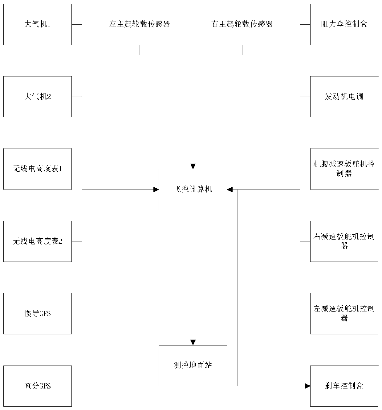
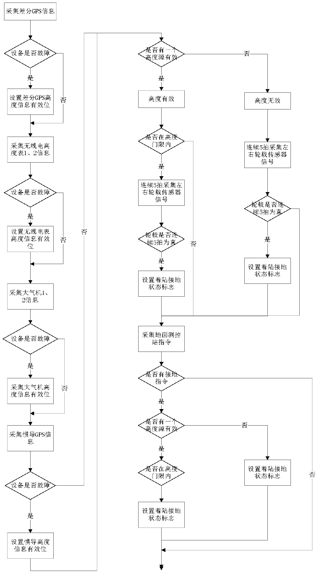
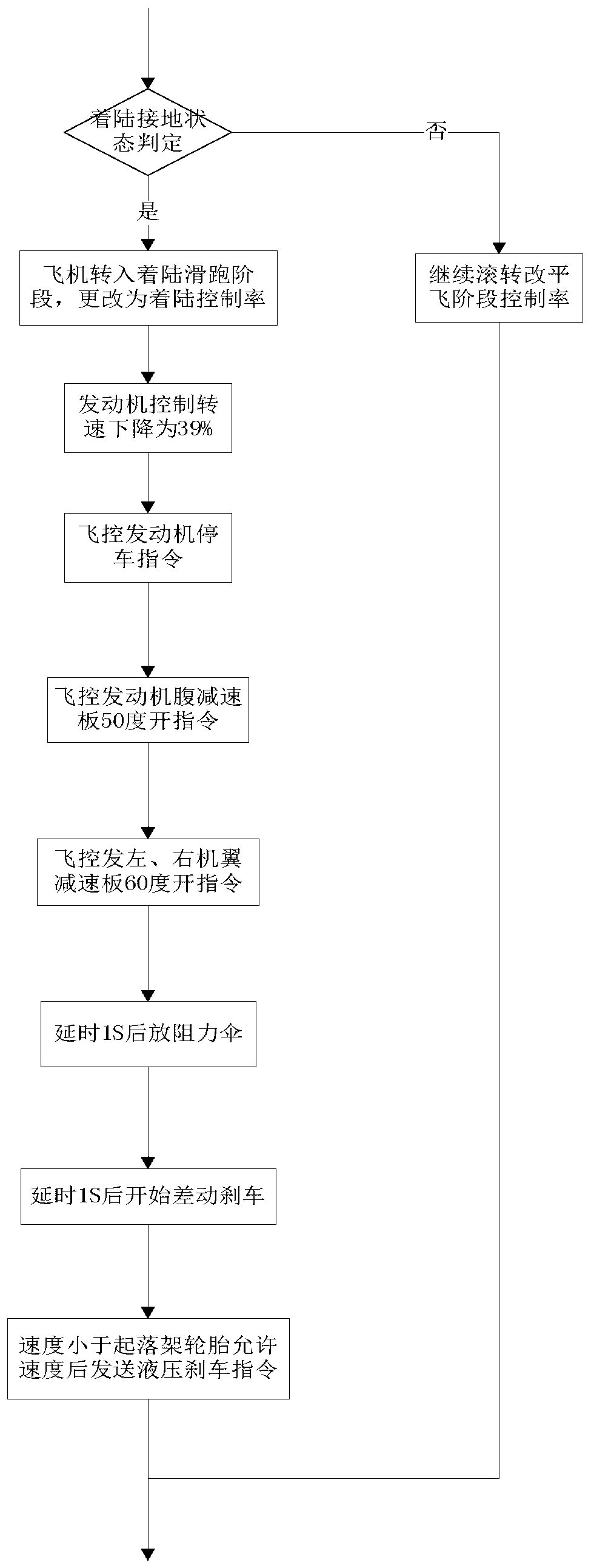
[0011] refer to figure 1 , figure 2 . According to the present invention, the high-altitude high-speed autonomous take-off and landing type UAV landing control system collects differential GPS information through the flight control computer, the altitude values ​​of the inertial navigation GPS, the atmospheric engine 1, the atmospheric engine 2, the radio altimeter 1, and the radio altimeter 2 and Validity signal, to determine whether the equipment is faulty, if yes, set differential GPS, inertial navigation GPS, radio altimeter 1, radio altimeter 2, and effective bit information of atmospheric machine altitude information, otherwise return to determine whether the equipment is faulty; according to differential GPS, The altitude value and validity signal of the inertial navigation GPS are used to judge whether there is an altitude source that is valid. If the altitude is valid, it is judged whether it is within the altitude threshold. If it is true for 5 consecutive shots, ...


PUM


Abstract

The invention discloses a high-altitude high-speed unmanned aerial vehicle landing and grounding state control method. The invention aims to provide a safer and more reliable control method. The control method of the invention is realized by following technical schemes: a high-altitude high-speed autonomous take-off and landing type unmanned aerial vehicle landing control system acquires the information of a differential GPS, and the altitude values and validity signals of an inertial navigation GPS, an atmospheric engine A, an atmospheric engine B, a radio altimeter A and a radio altimeter through a flight control computer, judges whether a certain device malfunctions, sets altitude information and valid bit information if the device malfunctions; whether one altitude source is valid is judged according to the altitude values and validity signals of the difference GPS and the inertial GPS, and if the altitude source is valid, whether the altitude source is within an altitude thresholdis judged, if the altitude source is within the altitude threshold, left main landing wheel load sensor and right main landing wheel load sensor signals are collected for 5 consecutive beats; and whether wheel load is real for 5 consecutive beats is judged, and if the wheel load is real for 5 consecutive beats, a landing and grounding state flag is set, and ground measurement and control system station commands are collected, and landing and grounding state operation is performed.

Description

technical field [0001] The technology relates to a method for comprehensive determination of the grounding status of high-altitude and high-speed autonomous take-off and landing unmanned aerial vehicles (UAVs) such as geodesy, meteorological observation, urban environment detection, earth resource exploration, and forest fire prevention. Background technique [0002] In the aviation industry, drones mainly include aircraft body, flight control system, data link system, launch recovery system, power supply system, etc. Statistics show that a large number of manned aircraft accidents occur during takeoff and landing. For autonomous take-off and landing UAVs, because the flight control computer and ground telemetry and remote control personnel have replaced the role of the pilot, the pilot lacks the ability to judge the landing and grounding status, and will automatically perform follow-up operations according to the status of the landing and grounding signs (such as releasing ...

Claims


Application Information

Patent Timeline
IPC IPC(8): G05D1/10G05D1/08
Inventor 梅颖徐龙盛小银吴佳美
Owner CHENGDU AIRCRAFT INDUSTRY GROUP
Learn More