
Gradient coil for magnetic resonance imaging and processing method thereof

A magnetic resonance imaging and gradient coil technology, applied in the direction of measuring magnetic variables, measuring devices, instruments, etc., can solve the problems of unsatisfactory use requirements, low gradient coil efficiency, low gradient strength, etc., to improve efficiency and gradient strength, improve Image quality and imaging speed, performance-enhancing effects

Active Publication Date: 2019-06-21
RAY PLUS MEDICAL TECH CO LTD
View PDF5 Cites 4 Cited by
  • Summary
  • Abstract
  • Description
  • Claims
  • Application Information

AI Technical Summary

Benefits of technology

This patented technology uses both an arc-shaped or planar coils with curled ends combined together to improve its effectiveness at generating strong signals while reducing unwanted noise from other parts around it. It also simplifies the process by eliminating any problems associated with traditional methods like spiral wires used in inductive devices such as MRI machines. Overall this results in improved signal intensity, reduced interference between different types of tissues within the body being imaged, better resolution images, faster data acquisition times, more accurate treatment techniques, less affected by changes caused by patient movement, etc., resulting in higher diagnosability rates for medical procedures.

Problems solved by technology

This patented technical problem addressed in this patent relates to improving the design of current gradients that can be applied during MR images due to their high inductive power consumption caused by the presence of many small conductors within them. These conductor elements cause noise interference with signal processing and degrade image resolution.

Method used


Image

  • Gradient coil for magnetic resonance imaging and processing method thereof
  • Gradient coil for magnetic resonance imaging and processing method thereof
  • Gradient coil for magnetic resonance imaging and processing method thereof

Examples


Embodiment Construction

[0032] The present invention will be further described below in conjunction with the accompanying drawings and specific embodiments, so that those skilled in the art can better understand the present invention and implement it, but the examples given are not intended to limit the present invention.

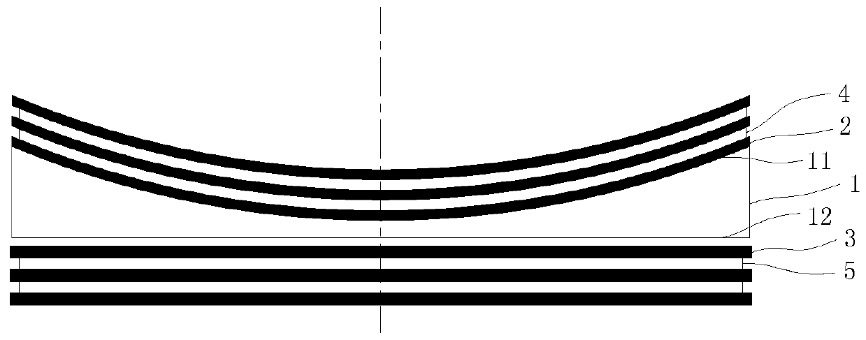
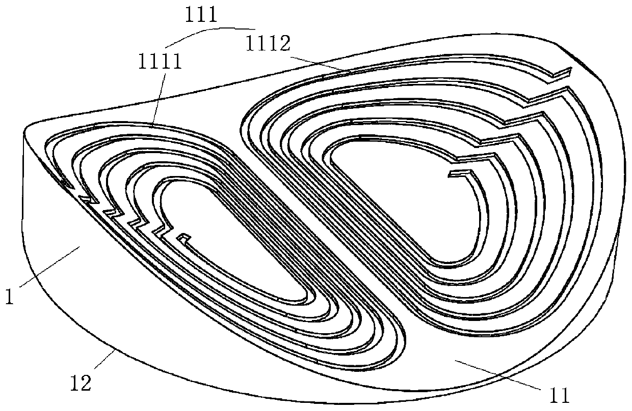
[0033] Such as figure 1 As shown, a gradient coil for magnetic resonance imaging includes an insulating base plate 1 and at least three sub-coils so as to form an X sub-coil, a Y sub-coil and a Z sub-coil respectively, at least one sub-coil is a curved surface coil 2, and the remaining sub-coils For the planar coil 3, the first surface of the insulating base plate 1 forms a curved surface 11 for fixing the curved coil 2, and the second surface forms a planar portion 12 for fixing the planar coil 3, and the curved coil 2 is fixed on the curved surface 11. The shape of the curved coil 2 is adapted to the shape of the curved surface 11 , that is, the overall curved surface shape of t...


PUM


Abstract

The invention discloses a gradient coil for magnetic resonance imaging and a processing method thereof. The gradient coil comprises an insulating base plate and at least three sub-coils; at least onesub-coil is a curved coil, and the remaining sub-coils are planar coils; the first surface of the insulating base plate forms a curved portion and the second surface forms a planar portion; the curvedcoil is fixed on the curved portion; the shape of the curved coil is adapted to the shape of the curved portion; and the planar coil is fixed on the planar portion. The invention also discloses a processing method for a gradient coil for magnetic resonance imaging. Deformation of the coil during the processing process can be effectively avoided, the processing precision and the performance of thegradient coil are improved, the efficiency and the gradient strength of the gradient coil are improved, image distortion can be effectively avoided, and the image quality is improved.

Description


Claims


Application Information

Patent Timeline
Owner RAY PLUS MEDICAL TECH CO LTD
Learn More