
Electric energy meter and electric energy meter box

A technology of electric energy meters and meter boxes, which is applied in the direction of measuring electric variables, measuring devices, instruments, etc., can solve the problems of complicated wiring operations, high design requirements, and high requirements for electric meter structure design, so as to improve installation efficiency, high efficiency, and easy operation easy effect

Pending Publication Date: 2019-06-21
ZHEJIANG CHINT INSTR & METER
View PDF0 Cites 3 Cited by
  • Summary
  • Abstract
  • Description
  • Claims
  • Application Information

AI Technical Summary

Problems solved by technology

[0002] At present, the smart meters in our country adopt two fixing methods, one is wall-mounted and the other is rail-mounted. The wall-mounted installation and replacement of the meter are inconvenient, and the wall-fixed meter needs to be connected to multiple Lines and wiring operations are complicated and need to be connected again when replacing the meter. In addition, the existence of multi-way terminals also requires relatively high structural design requirements for the meter.
The rail-type fixing method has the advantages of small size, easy installation, and easy networking, but it has higher requirements for the design of the circuit board of the meter and the design of the production tooling

Method used


Image

  • Electric energy meter and electric energy meter box
  • Electric energy meter and electric energy meter box
  • Electric energy meter and electric energy meter box

Examples


Embodiment Construction

[0031] The following is attached Figure 1-8 The given examples further illustrate the specific implementation of the electric energy meter of the present invention. The electric energy meter of the present invention is not limited to the description of the following embodiments.

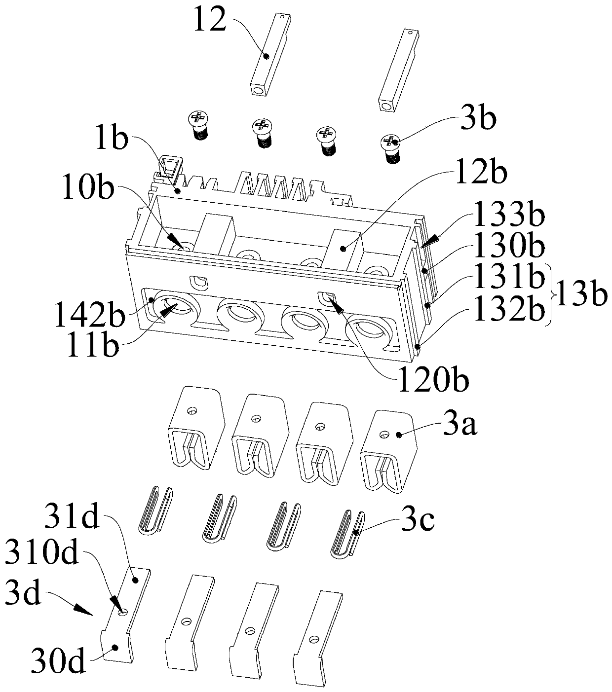
[0032] The electric energy meter of the present invention includes an electric energy meter casing 1; the electric energy meter casing 1 includes a casing main body 1a and a terminal block 1b; the terminal block 1b is arranged at one end of the casing main body 1a, and the terminal block 1b includes a set A plurality of assembly cavities 14b thereon, each assembly cavity 14b all comprises the assembly top wall 141b that is provided with the first opening 10b and the assembly cavity opening 140b, and the assembly top wall 141b and the assembly opening 140b are respectively arranged on the top of the assembly cavity 14b. At the upper and lower ends, each assembly cavity 14b is provided with a socket ...


PUM


Abstract

The present invention belongs to the field of electrical equipment and relates to an electric energy meter. The electric energy meter comprises an electric energy meter housing; the electric energy meter housing includes a housing main body and a terminal seat; the terminal seat is disposed at one end of the housing main body; the terminal seat includes a plurality of assembly cavities; each of the assembly cavities includes an assembly top wall and an assembly cavity opening, a first opening being formed in the assembly top wall; the assembly top wall and the assembly cavity opening are respectively disposed at the upper end and lower end of the assembly cavity; an insertion-connection female connector connected with the internal circuit of the electric energy meter is disposed in each assembly cavity, wherein the insertion-connection female connector is fixedly connected to the corresponding assembly top wall; the housing main body includes a main body opening corresponding to the assembly cavity opening; and the insertion-connection installation of the electric energy meter can be realized through the insertion-connection female connector. The invention also relates to an electric energy meter box. The electric energy meter box comprises an insertion-connection male connector; the insertion-connection male connector is in insertion-connection matching with the insertion-connection female connector of the electric energy meter; and the insertion-connection male connector is connected with an external connection wire; and the quick installation of the electric energy metercan be realized.

Description

technical field [0001] The invention relates to the field of electric equipment, in particular to an electric energy meter and an electric energy meter box, wherein a plug female head of the electric energy meter is mated with a plug male head of the electric energy meter box. Background technique [0002] At present, the smart meters in our country adopt two fixing methods, one is wall-mounted and the other is rail-mounted. The wall-mounted installation and replacement of the meter are inconvenient, and the wall-fixed meter needs to be connected to multiple Lines and wiring operations are complicated and need to be connected again when replacing the meter. In addition, the existence of multi-way terminals also requires relatively high structural design requirements for the meter. The rail-type fixing method has the advantages of small size, easy installation, and easy networking, but it has higher requirements for the design of the circuit board of the meter and the design ...

Claims


Application Information

Patent Timeline
Patent Type & Authority Applications(China)
IPC IPC(8): G01R11/04G01R11/02
Inventor 王芳王亚平
Owner ZHEJIANG CHINT INSTR & METER
Learn More