Construction method of hoisting steel truss arch members by using high and low pole beams through the narrow opening

A technology of shoulder pole beams and rods, which is applied in the construction field of hoisting steel truss arch rods through narrow closing dragon mouths by using high and low shoulder pole beams. problem, to avoid spreader collision effect

Active Publication Date: 2020-09-04
中铁十八局集团第二工程有限公司 +2
View PDF7 Cites 0 Cited by
  • Summary
  • Abstract
  • Description
  • Claims
  • Application Information

AI Technical Summary

Problems solved by technology

[0002] The basket-type steel truss arch bridge has a large span, and the cantilever assembly is usually carried out by cable-stayed buckle-hanging method. The rods can only be assembled under the steel truss arch, and then hoisted by cable cranes. However, the gap in the lower part of the arch bridge formed before closing is much smaller than the upper part. gap, and the length of both sides of the lower gap is less than the length of the upper rod to be hoisted, resulting in a narrow space for the rod to pass through, making it difficult for the rod to pass through a space smaller than its own length

Method used


Image

  • Construction method of hoisting steel truss arch members by using high and low pole beams through the narrow opening
  • Construction method of hoisting steel truss arch members by using high and low pole beams through the narrow opening
  • Construction method of hoisting steel truss arch members by using high and low pole beams through the narrow opening

Examples


Embodiment Construction

[0024] The present invention will be described in detail below in conjunction with the accompanying drawings and embodiments.

[0025] see Figure 1 to Figure 4 , a construction method for hoisting steel truss arch members through a narrow closing mouth by using high and low pole beams, according to the following steps:

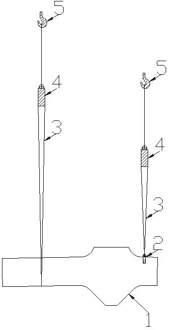
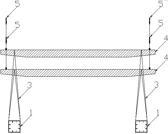
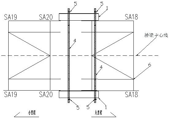
[0026] (1) Set two lifting points and lifting lugs 2 on the two rods 1 on both upstream and downstream sides, connect the lifting points 2 with a 50t sling 3, and connect the other end of the sling 3 to the pole beam 4;

[0027] (2) By controlling the length of the sling 3, the length of the sling 3 on the small mileage side is greater than the length of the sling 3 on the large mileage side. On the pole beam 4 on the mileage side;

[0028] (3) The pole beam 4 with a small mileage is connected to the main hook 5 of the cable crane with a small mileage, and the pole beam 4 on the side with a large mileage is connected to the main hook 5 with a large mileage,...


PUM


Abstract

The invention relates to a hoisting method of a steel truss arch rod piece, specifically a construction method of hoisting the steel truss arch rod piece by using a high and low shoulder pole beam through a narrow final closure. The method has the characteristics that a high and low shoulder pole beam system is formed before hoisting, the rod piece is placed at the outside of the projection of a steel truss arch on a site; the shoulder pole beam is the high and low shoulder pole beam formed by hanging belts with different length; the higher side of the shoulder pole beam penetrates through a narrow space firstly when passing through the narrow space, then stepped hoisting is carried out, so that a hoisting system is enabled to pass through the narrow space. According to the construction method of hoisting the steel truss arch rod piece by using the high and low shoulder pole beam through the narrow final closure, the situation that lifting appliances are excessively close to each otherwhen the rod piece is undergoing angle adjusting in the narrow space is avoided, so that the collision of the lifting appliances due to wind disturbance is avoided.

Description

technical field [0001] The invention relates to a hoisting method for a steel truss arch member, in particular to a construction method for hoisting a steel truss arch member by using high and low shoulder beams through a narrow closing gap. Background technique [0002] The basket-type steel truss arch bridge has a large span, and the cantilever assembly is usually carried out by cable-stayed buckle-hanging method. The rods can only be assembled under the steel truss arch, and then hoisted by cable cranes. However, the gap in the lower part of the arch bridge formed before closing is much smaller than the upper part. gap, and the length of both sides of the lower gap is less than the length of the upper rod to be hoisted, which results in a narrow space for the rod to pass through, making it difficult for the rod to pass through a space smaller than its own length. Contents of the invention [0003] The technical problem to be solved by the present invention is to provide...

Claims


Application Information

Patent Timeline
Patent Type & Authority Patents(China)
IPC IPC(8): E01D21/00
Inventor 于长彬张敏田波王佳孙立强扈晓立
Owner 中铁十八局集团第二工程有限公司
Why Eureka
Try Eureka