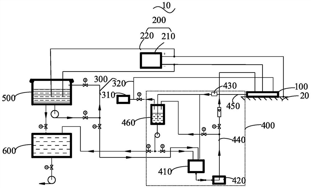
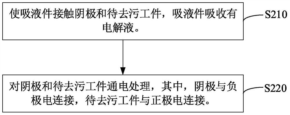
Decontamination system and decontamination method
A decontamination system and cathode technology, applied in electrolysis components, electrolysis process, etc., can solve the problem of more secondary waste liquid, etc., and achieve the effect of less secondary waste liquid
- Summary
- Abstract
- Description
- Claims
- Application Information
AI Technical Summary
Problems solved by technology
Method used
Image
Examples
Embodiment 1
[0079] The decontamination system of this embodiment is used to decontaminate the inner wall of the stainless steel storage tank. The LB124 surface pollution measuring instrument was used to measure the initial pollution level, and the pollution was mainly β pollution. The decontamination process is as follows:
[0080] (1) Place the liquid absorbing part in the casing to obtain the liquid absorbing assembly. The liquid-absorbing part is in contact with the cathode and the area 1 of the inner wall of the stainless steel storage tank, and the liquid-absorbing component is evacuated through a vacuum device, so that the liquid-absorbing part is in close contact with the cathode and the inner wall of the stainless steel storage tank. Wherein, the material of the liquid absorbing part is polyurethane foam. The cathode adopts a disc-shaped cerium tungsten electrode, and the cathode area is 50cm 2 , the distance between the cathode and the inner wall of the stainless steel storage...
Embodiment 2
[0087] The decontamination system of this embodiment is used to decontaminate the outer wall of a heavily polluted stainless steel liquid storage tank. The LB124 surface pollution measuring instrument was used to measure the initial pollution level, and the pollution was mainly β pollution. The decontamination process is as follows:
[0088] (1) Place the liquid absorbing part in the casing to obtain the liquid absorbing assembly. The liquid-absorbing part is in contact with the cathode and the area 1 of the outer wall of the stainless steel storage tank, and the liquid-absorbing component is evacuated through a vacuum device, so that the liquid-absorbing part is in close contact with the cathode and the outer wall of the stainless steel storage tank. Wherein, the material of the liquid absorbing part is wood cellulose. The cathode adopts a mesh titanium iridium-plated electrode, and the cathode area is 50cm 2 , the distance between the cathode and the outer wall of the sta...
Embodiment 3
[0095] The decontamination system of this embodiment is used to decontaminate a heavily polluted stainless steel cover plate. The LB124 surface pollution measuring instrument was used to measure the initial pollution level, and the pollution was mainly β pollution. The decontamination process is as follows:
[0096] (1) Place the liquid absorbing part in the casing to obtain the liquid absorbing assembly. The liquid-absorbing part is in contact with the cathode and the area 1 of the stainless steel cover plate of the workpiece to be decontaminated, and the liquid-absorbing component is evacuated through a vacuum device, so that the liquid-absorbing part is in close contact with the cathode and the inner surface of the workpiece to be decontaminated. Wherein, the material of the liquid absorbing part is polyacrylate. The cathode adopts a mesh-shaped silver-tungsten electrode, and the cathode area is 200cm 2 , The distance between the cathode and the stainless steel cover pla...
PUM
| Property | Measurement | Unit |
|---|---|---|
| thickness | aaaaa | aaaaa |
| area | aaaaa | aaaaa |
Abstract
Description
Claims
Application Information
 - R&D
- Intellectual Property
- Life Sciences
- Materials
- Tech Scout
- Unparalleled Data Quality
- Higher Quality Content
- 60% Fewer Hallucinations
Browse by: Latest US Patents, China's latest patents, Technical Efficacy Thesaurus, Application Domain, Technology Topic, Popular Technical Reports.
© 2025 PatSnap. All rights reserved.Legal|Privacy policy|Modern Slavery Act Transparency Statement|Sitemap|About US| Contact US: help@patsnap.com


