
Piezoelectric generating shoe

A technology of piezoelectric power generation and piezoelectric sheets, applied in footwear, clothing, applications, etc., can solve the problems of low power-to-electricity conversion efficiency, achieve large power generation, improve power-to-electricity conversion efficiency, and be easy to produce

Pending Publication Date: 2019-06-21
FOURTH MILITARY MEDICAL UNIVERSITY
View PDF1 Cites 1 Cited by
  • Summary
  • Abstract
  • Description
  • Claims
  • Application Information

AI Technical Summary

Problems solved by technology

[0006] In view of the deficiencies and defects of the above-mentioned prior art, the purpose of the present invention is to provide a piezoelectric power generation shoe, which solves the technical problem of low power-to-electricity conversion efficiency of the piezoelectric power generation shoe in the prior art

Method used


Image

  • Piezoelectric generating shoe
  • Piezoelectric generating shoe
  • Piezoelectric generating shoe

Examples


Embodiment

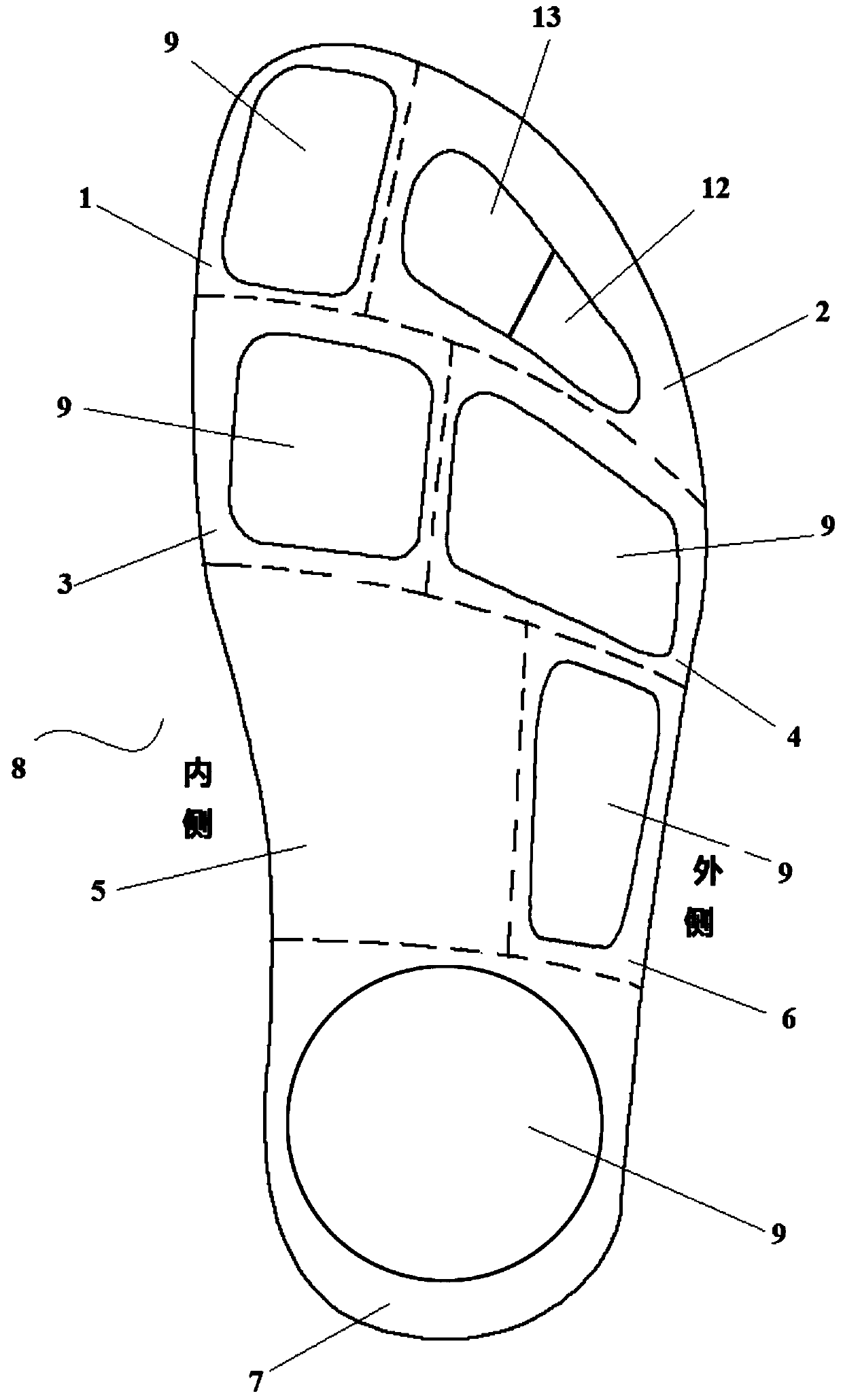
[0036] Following the above technical solution, this embodiment provides a piezoelectric power generation shoe, such as figure 1 with figure 2 As shown, it includes a sole 8. The sole 8 is provided with a phalanx region, a metatarsal region, an arch region and a heel region 7 corresponding to the sole of the human foot from the front end to the rear end. The phalanx region includes the inner side of the sole 8 The first phalanx region 1 and the second to fifth phalanx regions 2 located on the outer side of the sole 8; the metatarsal region includes the first and second metatarsal regions 3 located on the inner side of the sole 8 and the third to second phalanx regions located on the outer side of the sole 8 The five metatarsal area 4; the arch area includes the inner arch area 5 located on the inner side of the sole 8 and the outer arch area 6 located on the outer side of the sole 8;

[0037] In this embodiment, the division and determination of the 8 partitions of the sole are ba...

Embodiment 2

[0046] This embodiment provides a piezoelectric power generation shoe, such as figure 1 with image 3 As shown, the piezoelectric power-generating shoe is basically the same as Example 1. The solution in this embodiment is used as a further optional solution of Example 1, and the user can choose to set or not set according to needs. Specifically, the bottom of the sole 8 of the heel area 7 is provided with a high heel 10, and the high heel 10 is provided with a piezoelectric transducer 11, and the piezoelectric transducer 11 includes a high heel 10 The rigid housing 1101 and the pressure-bearing cover plate 1102 covered on the rigid housing 1101, the pressure-bearing cover plate 1102 shown is arranged in the heel area 7 to replace the pressure gasket, and the rigid housing 1101 is also installed There is a transmission mechanism 1103 and based on d 15 The piezoelectric transduction mechanism 1104 in the energy conversion mode; the force transmission mechanism 1103 can convert th...


PUM


Abstract

The invention provides a piezoelectric generating shoe which comprises a shoe sole, wherein piezoelectric pads are arranged in a first phalanx zone, first and second metatarsal bone zones, third to fifth metatarsal bone zones, an external arch zone and a heel zone; the thickness of the piezoelectric pads in the first and second metatarsal bone zones is more than or equal to the thickness of the piezoelectric pads in the heel zone; the thickness of the piezoelectric pads in the heel zone is more than the thickness of the piezoelectric pads in the third to fifth metatarsal bone zones; the thickness of the piezoelectric pads in the third to fifth metatarsal bone zones is more than or equal to the thickness of the piezoelectric pads in the first phalanx zone; the thickness of the piezoelectricpads in the first phalanx zone is more than the thickness of the piezoelectric pads in the external arch zone. In the piezoelectric generating shoe provided by the invention, the piezoelectric pads in different thicknesses are arranged according to the physiological property of different zones of the shoe sole receiving different pressures, the layout is reasonable, the power-electricity conversion is extremely realized and the power-electricity efficiency of the piezoelectric generating shoe is increased.

Description

Technical field [0001] The invention belongs to the field of daily necessities, and relates to power-generating shoes, in particular to piezoelectric power-generating shoes. Background technique [0002] In daily life, when people are walking, they consume energy all the time and dissipate this energy in the environment. At present, some shoes have appeared, using the conversion device inside the shoes to convert the kinetic energy of the human body into electrical energy. However, the conversion devices of these shoes often use complex mechanical structures, and the mechanical transmission is prone to wear and failure. If these shoes can store the converted electric energy and be suitable for charging low-power electronic devices such as mobile phones and MP3s, these shoes will be favored by people and have broad market prospects. [0003] The prior art discloses a piezoelectric power-generating shoe, which includes a sole, the forefoot of the sole is provided with more than two...

Claims


Application Information

Patent Timeline
Patent Type & Authority Applications(China)
IPC IPC(8): A43B3/00
CPCY02B40/00
Inventor 费霏刘文博费舟
Owner FOURTH MILITARY MEDICAL UNIVERSITY
Learn More