Fabricated building outer protective frame and fabricated building construction method

An external protection and assembly technology, applied in the field of scaffolding, can solve the problems of complex frame structure and operation, imperfect design performance, too large reserved holes in the wall, etc., to achieve simple and reliable connection, eliminate safety hazards, and facilitate The effect of construction

Pending Publication Date: 2019-06-18
CHINA METALLURGICAL CONSTR ENG GRP
View PDF11 Cites 0 Cited by
  • Summary
  • Abstract
  • Description
  • Claims
  • Application Information

AI Technical Summary

Problems solved by technology

Among them, floor-standing steel pipe scaffolding and cantilevered scaffolding are traditional forms, which have disadvantages such as difficulty in construction, limited height, and excessively large reserved holes in the wall. The integral structure and operation of the frame are complex and require high
What is suitable to use at present is the tool-type outer protective frame of tool-type scaffolding, and there are also relevant references in the prior art, such as: CN108756196A, CN206376507U, CN106677509A, CN207110421U, CN108868096A, but still there is inconvenience in construction in the relevant outer protective frame, and the design performance is not perfect question

Method used


Image

  • Fabricated building outer protective frame and fabricated building construction method
  • Fabricated building outer protective frame and fabricated building construction method
  • Fabricated building outer protective frame and fabricated building construction method

Examples


Embodiment Construction

[0047] The specific implementation manners of the present invention will be further described in detail below in conjunction with the accompanying drawings.

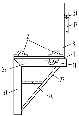
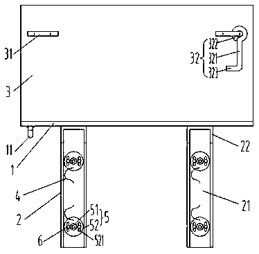
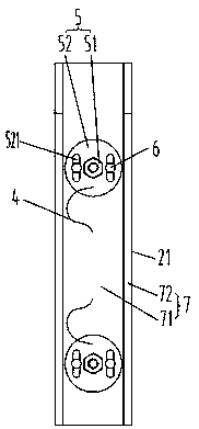
[0048] see Figure 1-5, the prefabricated building exterior protective frame of specific embodiment, comprises horizontal pedal 1, and the lower surface of described pedal 1 is connected with two tripods 2 for connecting the wall, and two tripods 2 are spaced apart along the length direction of pedal 1 Setting, the upper surface of the pedal 1 is connected with a vertical front guard plate 3; the tripod 2 includes a vertical shelf 21 and a horizontal shelf 22 connected in an inverted L shape, and the horizontal shelf 22 is connected to the pedal 1 is connected to the lower surface and is perpendicular to the length direction of the pedal 1. The vertical shelf 21 is flush with the wall side of the pedal 1 so as to be connected to the wall. The front guard plate 3 is connected to the wall side of the pedal 1. The opposite...


PUM


Abstract

The invention relates to a fabricated building outer protective frame and a fabricated building construction method. The fabricated building outer protective frame comprises a horizontal footboard, atleast two tripods used for connecting a wall body are connected to the lower surface of the footboard, the various tripods are arranged at intervals in the length direction of the footboard, and a main vertical protective plate is connected to the upper surface of the footboard; each tripod comprises a vertical frame plate and a horizontal frame plate, each vertical frame plate and each horizontal frame plate are mutually connected and in a reverse L shape, the horizontal frame plates are connected with the lower surface of the footboard, the footboard are parallel and level with the side surface, close to a wall, of the vertical frame plates, and the footboard is parallel and level with the relative side surface of the side surface, close to a wall, of the main protective plate; two through holes are vertically formed in each vertical frame plate at interval, soft ropes used by matching with the through holes one to one are connected to the vertical frame plates, one ends of the softropes is are connected with the vertical frame plates, the other ends of the soft ropes are connected with nuts, and the nuts can correspond to the corresponding through holes within the limited moving range because of being connected with the soft ropes. According to the fabricated building outer protective frame, the connection between nuts and frame bodies is maintained, and the effects of more convenient construction and improved safety can be achieved.

Description

technical field [0001] The invention belongs to the technical field of scaffolding supported by building structures in buildings, and in particular relates to an assembled building external protective frame and an assembled building construction method. Background technique [0002] In the construction of the assembled integral concrete structure, the external protection system can use floor-standing steel pipe scaffolding, cantilevered scaffolding, integral operating platform, fixed attachment protection frame, integral attachment lifting protection frame, tool-type scaffolding, etc. form. Among them, floor-standing steel pipe scaffolding and cantilevered scaffolding are traditional forms, which have disadvantages such as difficulty in construction, limited height, and excessively large reserved holes in the wall. What is suitable to use at present is the tool-type outer protective frame of tool-type scaffolding, and there are also relevant references in the prior art, suc...

Claims


Application Information

Patent Timeline
IPC IPC(8): E04G3/20E04G5/04E04G5/00
Inventor 霍定刚刘博姜国祥郭江范彬朱华川
Owner CHINA METALLURGICAL CONSTR ENG GRP
Why Eureka
Try Eureka