
co for high voltage direct current grid 2 switch

A technology of DC network and switch, applied in the direction of high voltage/large current switch, electric switch, high voltage air circuit breaker, etc., can solve the problem of not providing resonant circuit and so on

Active Publication Date: 2022-03-15
SUPERGRID INSTITUTE SAS
View PDF10 Cites 0 Cited by
  • Summary
  • Abstract
  • Description
  • Claims
  • Application Information

AI Technical Summary

Problems solved by technology

The patent application does not provide information on how to implement it with a resonant circuit

Method used


Image

  • co for high voltage direct current grid  <sub>2</sub> switch
  • co for high voltage direct current grid  <sub>2</sub> switch
  • co for high voltage direct current grid  <sub>2</sub> switch

Examples


Embodiment Construction

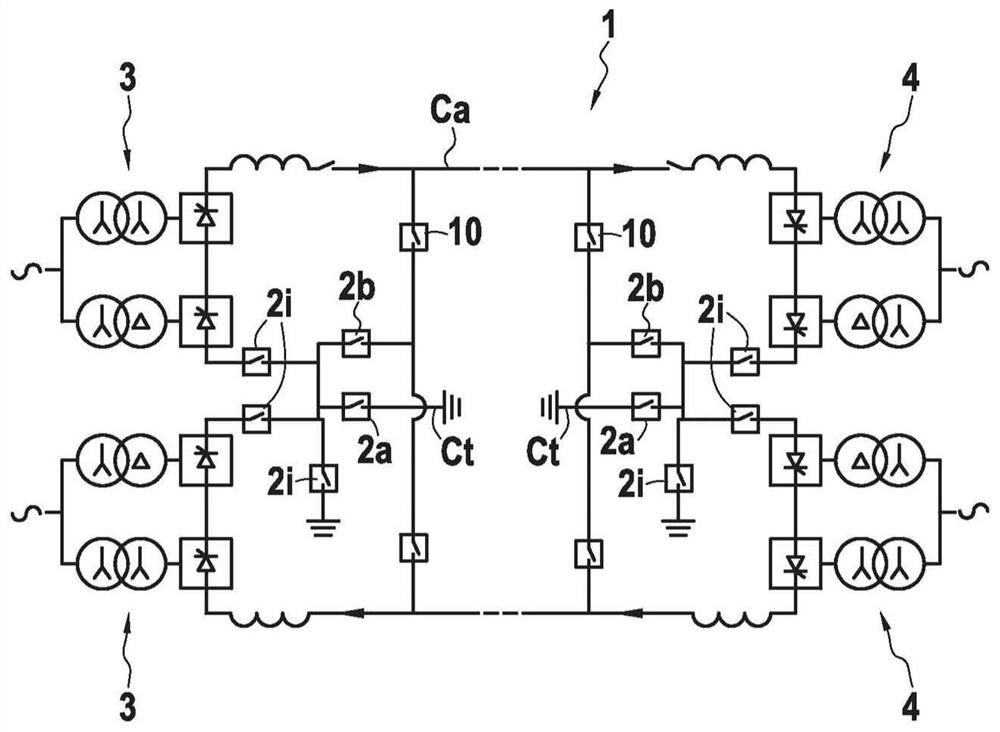
[0039] As an example, figure 1 Shown is a high voltage or medium voltage direct current transmission network 1 utilizing at least one and usually a plurality of HVDC or MVDC gas insulated switches 2i for interrupting direct current in the network lines according to the invention. In conventional manner, such a DC transmission network 1 comprises an AC / DC converter 3 at at least one end and a DC / AC converter 4 at the other end. Since the converters 3, 4 do not specifically form part of the invention and are well known to those skilled in the art, they are not described in detail.

[0040] Reference 2i is given to a switch according to the invention, where i varies from a, b, . . . to n. These switches 2i according to the invention are connected between the converters 3, 4 and points of the network 1 in order to direct power from one point of the network to another. For example, in case of a fault on one pole or a prolonged maintenance operation on a network pole, the switch 2...


PUM


Abstract

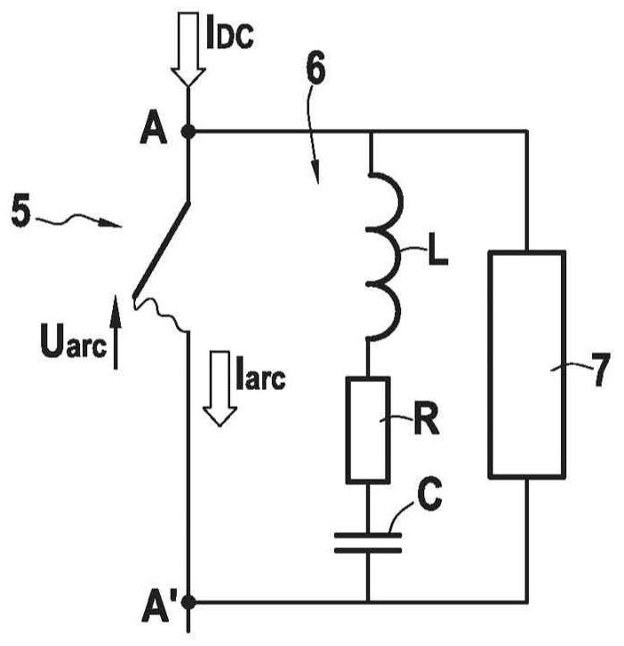
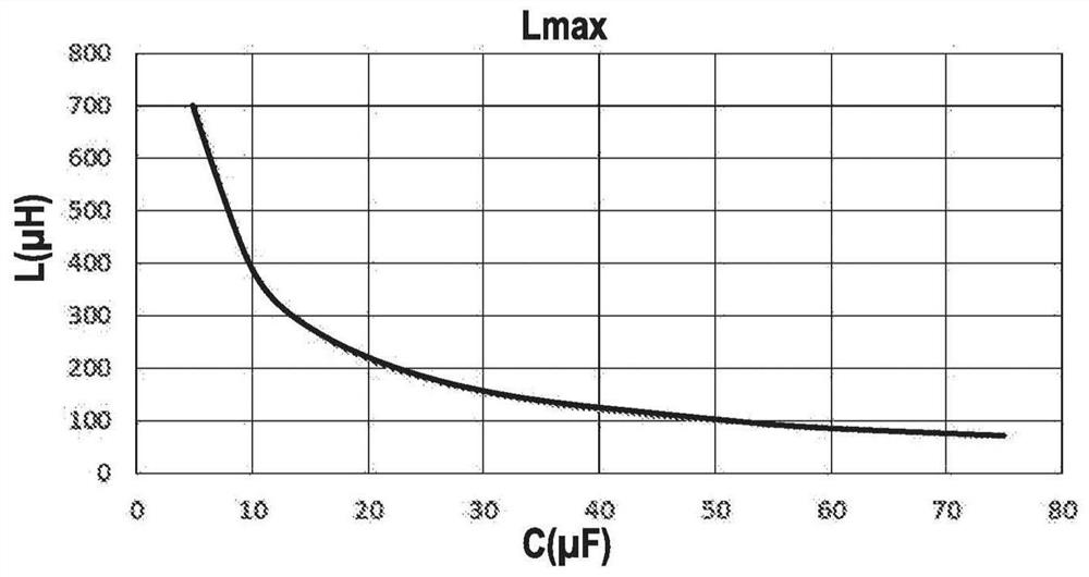
The invention relates to a switch for a high-voltage or medium-voltage direct current network, the switch comprising a DC circuit breaker (5) with a sealed enclosure containing a gaseous fluid comprising a temperature measured at a temperature of 20°C in At least 70% by volume of carbon dioxide at a pressure in the range of 0.65 MPa to 1.1 MPa, and a resonant circuit having a value of capacitance (C) in μF and less than 2700×C in μH ‑0.84 inductance (L).

Description

technical field [0001] The present invention relates to the general technical field of high voltage direct current (HVDC) transmission networks or medium voltage direct current (MVDC) transmission networks. [0002] More specifically, the present invention relates to HVDC or MVDC gas insulated switches for interrupting direct current (DC) in lines of a high or medium voltage DC transmission network. [0003] A particularly advantageous application of the invention lies in the technical field of high-voltage or medium-voltage DC networks for switching power from one path of the network to another, for example in the event of a fault on a pole, or in the network In case of prolonged maintenance operations on the pole. Background technique [0004] In DC networks, it is known to use switches comprising a branch circuit with a DC circuit breaker with active circuit breaking members enclosed in a sealed enclosure containing a gaseous fluid. The prior art proposes many technical...

Claims


Application Information

Patent Timeline
Patent Type & Authority Patents(China)
IPC IPC(8): H01H33/59H01H33/22
CPCH01H33/22H01H33/596H01H2033/566
Inventor 克里斯托弗·克勒索
Owner SUPERGRID INSTITUTE SAS
Learn More