A vehicle slam mapping method and system
A technology for vehicles and maps, which is applied in the field of SLAM mapping methods and systems for vehicles, and can solve the problems of lack of environmental information on maps and low success rate of mapping, etc.
- Summary
- Abstract
- Description
- Claims
- Application Information
AI Technical Summary
Problems solved by technology
Method used
Image
Examples
Embodiment 1
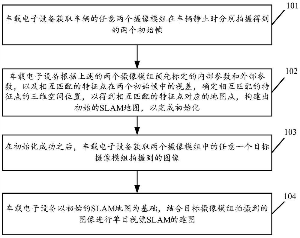
[0073] see figure 1 , figure 1 It is a schematic flowchart of a vehicle SLAM mapping method disclosed in an embodiment of the present invention. in, figure 1 The described vehicle SLAM mapping method is applicable to vehicle-mounted electronic equipment such as a vehicle-mounted computer and an electronic control unit (Electronic Control Unit, ECU), and is not limited in the embodiments of the present invention. Such as figure 1 As shown, the SLAM mapping method of the vehicle may include the following steps:
[0074] 101. The on-vehicle electronic device acquires two initial frames respectively captured by any two camera modules of the vehicle when the vehicle is stationary.
[0075] In the embodiment of the present invention, the viewing ranges of the two camera modules overlap at least partially. As an optional implementation manner, the above two camera modules may be any two camera modules in a multi-eye camera system. The multi-eye camera system can include three o...
Embodiment 2
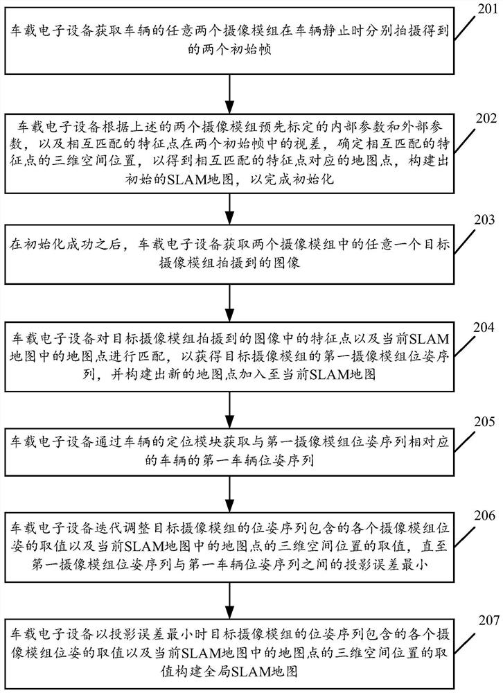
[0093] see figure 2 , figure 2 It is a schematic flowchart of another vehicle SLAM mapping method disclosed in the embodiment of the present invention. Such as figure 2 As shown, the SLAM mapping method of the vehicle may include the following steps:
[0094] 201. The on-vehicle electronic device acquires two initial frames respectively captured by any two camera modules of the vehicle when the vehicle is stationary.
[0095] In the embodiment of the present invention, the above-mentioned two camera modules may be any two camera modules in a multi-eye camera system, and the focal lengths and field angles of the two camera modules may be the same or different. However, due to the large number of camera modules in the multi-camera system, in order to reduce the amount of image data processing and speed up the processing time, a camera module with a fixed focal length is generally selected. Further, in order to expand the observation distance that can be covered, different...
Embodiment 3
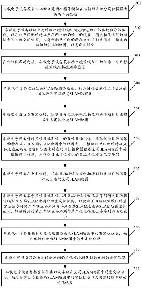
[0114] see image 3 , image 3 It is a schematic flowchart of another vehicle SLAM mapping method disclosed in the embodiment of the present invention. Such as image 3 As shown, the SLAM mapping method of the vehicle may include the following steps:
[0115] Steps 301 to 304 are the same as steps 101 to 104, wherein the specific implementation of step 304 can be as shown in steps 204 to 206, and the following content will not be repeated.
[0116] 305. During relocation, the vehicle-mounted electronic device acquires multiple frames of target images captured by the target camera module and the aforementioned global SLAM map.
[0117] In the embodiment of the present invention, the global SLAM map is a digital description of the real environment. After the global SLAM map is constructed, the vehicle electronic device can reuse the global SLAM map. Similar to the way humans use maps for positioning, on-board electronic devices can locate the position of the vehicle in the g...
PUM
 Abstract
Description
Claims
Application Information
 - R&D Engineer
- R&D Manager
- IP Professional
- Industry Leading Data Capabilities
- Powerful AI technology
- Patent DNA Extraction
Browse by: Latest US Patents, China's latest patents, Technical Efficacy Thesaurus, Application Domain, Technology Topic, Popular Technical Reports.
© 2024 PatSnap. All rights reserved.Legal|Privacy policy|Modern Slavery Act Transparency Statement|Sitemap|About US| Contact US: help@patsnap.com


