
Method for convexity online control over ultrathin cast rolling strip steel

A strip crown and cast strip technology, applied in the direction of contour control, etc., can solve the problem that the unit crown flatness control of the strip is not considered, and the feedforward control method cannot be applied to the strip crown control of a single-stand rolling mill. Taking into account issues such as hysteresis effects

Pending Publication Date: 2019-06-14
SHAGANG GROUP +2
View PDF7 Cites 2 Cited by
  • Summary
  • Abstract
  • Description
  • Claims
  • Application Information

AI Technical Summary

Problems solved by technology

At the same time, the existing hot-rolled strip crown control system relies on the tandem rolling mill, and the feed-forward control method adopted cannot be applied to the strip crown control of a single-stand rolling mill
[0006] Patent document CN200710194281.9 ("The crown control device of the hot rolling mill and its control method") discloses a method for controlling the strip crown of the Stekel rolling mill, that is, the production of 2~ 10mm hot-rolled strip steel. According to the different rolling passes of the strip steel, the front and rear crown detection devices of the Stekel mill are used to compare with the target crown or locked crown set for each pass. The on-line control of feed and feedback realizes the control of the crown of the strip, but this implementation is used in the Stekel rolling mill with reversible multi-pass reciprocating rolling, and does not take into account the flatness caused by the change of the unit crown of the strip. Straightness control, at the same time, the hysteresis effect caused by the distance between the actuator and the detection device is not considered in its feedback control
The hot-rolled strip crown control method disclosed in the patent document JP62168608 is to install a crown detection device at the entrance of the hot continuous rolling mill, and control the crown of the final product by adjusting the entrance crown. The rolling mill is different from the single-stand rolling mill that rolls twin casting rolls to produce ultra-thin cast strip

Method used


Image

  • Method for convexity online control over ultrathin cast rolling strip steel
  • Method for convexity online control over ultrathin cast rolling strip steel
  • Method for convexity online control over ultrathin cast rolling strip steel

Examples


Embodiment Construction

[0069] In order to make the purpose, technical solutions and advantages of the embodiments of the present invention clearer, the technical solutions of the embodiments of the present invention will be clearly and completely described below. Apparently, the described embodiments are some, not all, embodiments of the present invention. Based on the described embodiments of the present invention, all other embodiments obtained by persons of ordinary skill in the art without creative efforts shall fall within the protection scope of the present invention.

[0070] Unless otherwise defined, the technical terms or scientific terms used in the present disclosure shall have the usual meanings understood by those skilled in the art to which the present invention belongs.

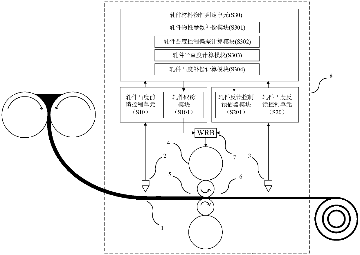
[0071] figure 1 It is a schematic diagram of the method for realizing the on-line control of the ultra-thin cast-rolled strip crown in the present invention. The rolling equipment of the present invention includes ...


PUM


Abstract

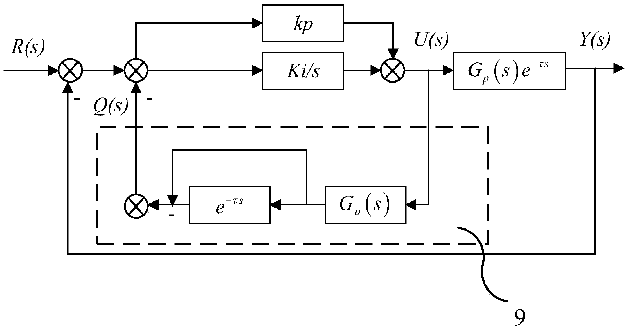
The invention provides an online closed-loop control method for convexity of a rolled piece in the rolling machining process of ultrathin cast rolling strip steel. According to the strip convexity measured by detection devices on sides of an inlet and an outlet of a rack of a rolling mill, a feed forward controller with strip micro tracking and a feedback controller with a predictor are used for calculating roll bending force corrected value, a working roll bending device is controlled in real time, convexity online control in the rolling process of the ultrathin cast rolling strip steel of double cast rolls is achieved, and the requirements for quality of product convexity from different steel grades and specifications are met.

Description

technical field [0001] The invention relates to a method for on-line closed-loop control of the convexity of rolled pieces in the rolling process of ultra-thin cast strip steel. Background technique [0002] Ultra-thin casting strip steel is a new technology that uses liquid steel as raw material and two casting rolls with opposite rotation directions as crystallizers to directly produce ultra-thin casting strip with liquid steel. Its characteristic is that the liquid metal is directly injected into the gap of the rotating casting roll, so that it can withstand pressure processing and plastic deformation while the crystal is solidified, and complete the forming process from liquid steel to ultra-thin cast strip. The ultra-thin cast strip produced After the strip passes through the hot rolling mill, the plastic processing process of the cast strip is completed to form a finished rolled strip that meets the size specifications required by the user. This method can produce 1.2...

Claims


Application Information

Patent Timeline
IPC IPC(8): B21B37/28
Inventor 王哲冯玉涛刘俭施一新马毅周东升李化龙顾小祥
Owner SHAGANG GROUP
Learn More