Eureka AIR delivers breakthrough ideas for toughest innovation challenges, trusted by R&D personnel around the world.

A system for controlling a light source to capture images to realize action execution

A technology for performing actions and capturing images. It is used in image communication, TV system components, and color TV components. It can solve the problems of high maintenance cost and high cost, and achieve low maintenance cost, low cost, and overall maintenance. low cost effect

Pending Publication Date: 2019-06-11
扬州哈工科创机器人研究院有限公司
View PDF4 Cites 1 Cited by
  • Summary
  • Abstract
  • Description
  • Claims
  • Application Information

AI Technical Summary

Problems solved by technology

[0004] At present, motion capture systems such as mechanical motion capture systems, acoustic motion capture systems, and electromagnetic motion capture systems are generally used for motion capture, but most motion capture systems are expensive and maintenance costs are high

Method used


Image

  • A system for controlling a light source to capture images to realize action execution
  • A system for controlling a light source to capture images to realize action execution

Examples


specific Embodiment approach 1

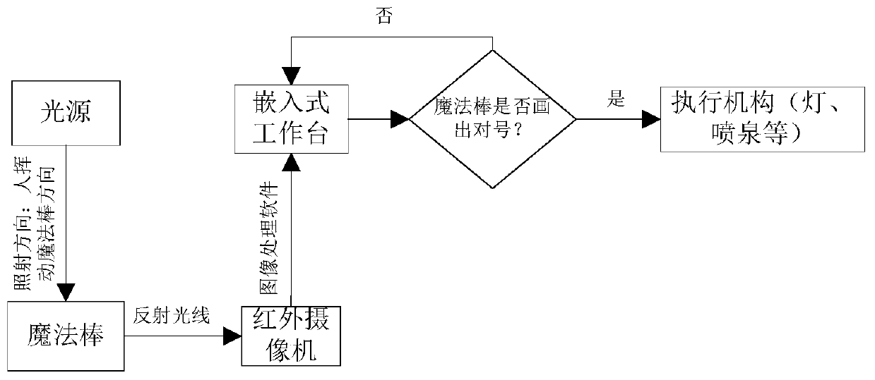
[0019] Specific implementation mode one: combine figure 1 and figure 2 Describe this embodiment, a system for controlling a light source to capture images to implement actions in this embodiment, including a light source, a magic wand, an infrared camera, an embedded workstation, and an action execution mechanism;

[0020] The magic wand includes a long rod and a mirror installed at the end of the long rod;

[0021] The embedded workstation has a computer for image information processing inside, and the infrared camera and the action actuator are all connected to the computer;

[0022] The infrared camera is used to photograph the visible light source reflected by the reflector at the end of the magic wand waved to obtain image information, and send the image information to the computer, and the computer processes and recognizes the visible light reflected by the magic wand and Whether the predetermined pattern inside the computer matches, if it matches, the computer contro...

specific Embodiment approach 2

[0031] Specific implementation mode two: combination figure 1 , figure 2 and Specific Embodiment 1 Describe this embodiment. In this embodiment, a system that controls a light source to capture images to implement actions, the computer determines that the infrared camera is in the process of moving the magic wand according to its internal image information and visible light imaging positioning algorithm. The process of the reflected light source movement position information specifically includes: using the visible light imaging positioning algorithm to determine the relative distance and relative angle of the light source movement reflected by the infrared camera during the movement of the magic wand from the image information; The relative distance and relative angle of the reflected light source during the movement of the wand determine the position information of the infrared camera during the movement of the magic wand.


PUM


Abstract

The invention discloses a system for controlling a light source capture to realize action execution, and belongs to the technical field of optical action control. The system comprises the light source, a magic wand, an infrared camera, an embedded workstation and an action executing mechanism. The magic wand comprises a long rod and a reflector mounted at the end part of the long rod; a computer used for image information processing is arranged in the embedded workstation, and the infrared camera and the action executing mechanism are both connected with the computer. The infrared camera is used for shooting the visible light source reflected by the waved magic wand end reflector to thereby obtain the image information and send the image information to the computer; and the computer processes and identifies whether the visible light reflected by the magic wand is matched with the preset pattern in the computer or not, if yes, the computer controls the action executing mechanism to execute corresponding actions, and if not, the system identifies the visible light reflected by the magic wand again. The overall maintenance cost of the action execution system is lower.

Description

technical field [0001] The invention relates to a system for controlling a light source to capture images, and belongs to the technical field of optical action control. Background technique [0002] Optical motion capture is a typical representative of machine vision applications in recent years. Motion capture is a technology that accurately measures and records the trajectory or posture of an object in a real three-dimensional space in real time, and reconstructs the motion state of the moving object at each moment in a virtual three-dimensional space. Optical motion capture is based on the principle of computer vision, and multiple high-speed cameras monitor and track the feature points of the target object from different angles, thereby performing motion capture technology. Theoretically speaking, for any point in space, as long as it can be seen by two cameras at the same time, the position of the point in space at this moment can be determined. When the camera shoots...

Claims


Application Information

Patent Timeline
Patent Type & Authority Applications(China)
IPC IPC(8): H04N5/33H04N5/225
Inventor 张广才马浚峰赵小东衣超寇江伟
Owner 扬州哈工科创机器人研究院有限公司
Why Eureka
Eureka Blog
Learn More