
Display assembly, installation method thereof and terminal

A display component and terminal technology, applied in nonlinear optics, instruments, optics, etc., can solve the problems of increasing the chance of broken screen, not so beautiful, false touch, etc.

Inactive Publication Date: 2019-06-07
HUAWEI DEVICE CO LTD
View PDF4 Cites 0 Cited by
  • Summary
  • Abstract
  • Description
  • Claims
  • Application Information

AI Technical Summary

Problems solved by technology

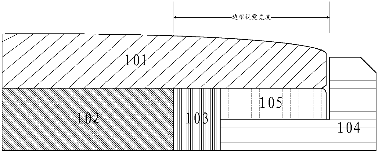
[0002] Nowadays, the screen-to-body ratio of terminal display screens has become the selling point of current products, but the structural design of current terminal products has problems such as light leakage, false touches, and increased chances of broken screens, and it is still impossible to achieve true borderless
[0003] At present, TP-LCD is installed from top to bottom. The product shell supports TP-LCD steps hidden inside the product. The structure of TP-LCD is: the length and width of the glass cover are larger than that of the liquid crystal display (LCD) Size: The overall size of the LCD is larger than the display area, so there is a problem of displaying black borders, which leads to the terminal displaying too large a non-display area with black borders, resulting in a low screen-to-body ratio, and the appearance design (industrlal design, ID) is not so beautiful

Method used


Image

  • Display assembly, installation method thereof and terminal
  • Display assembly, installation method thereof and terminal
  • Display assembly, installation method thereof and terminal

Examples


Embodiment Construction

[0022] In the embodiment of the present invention, the terminals include but are not limited to devices with screens such as mobile phones, smart watches, smart bracelets, and smart wristbands.

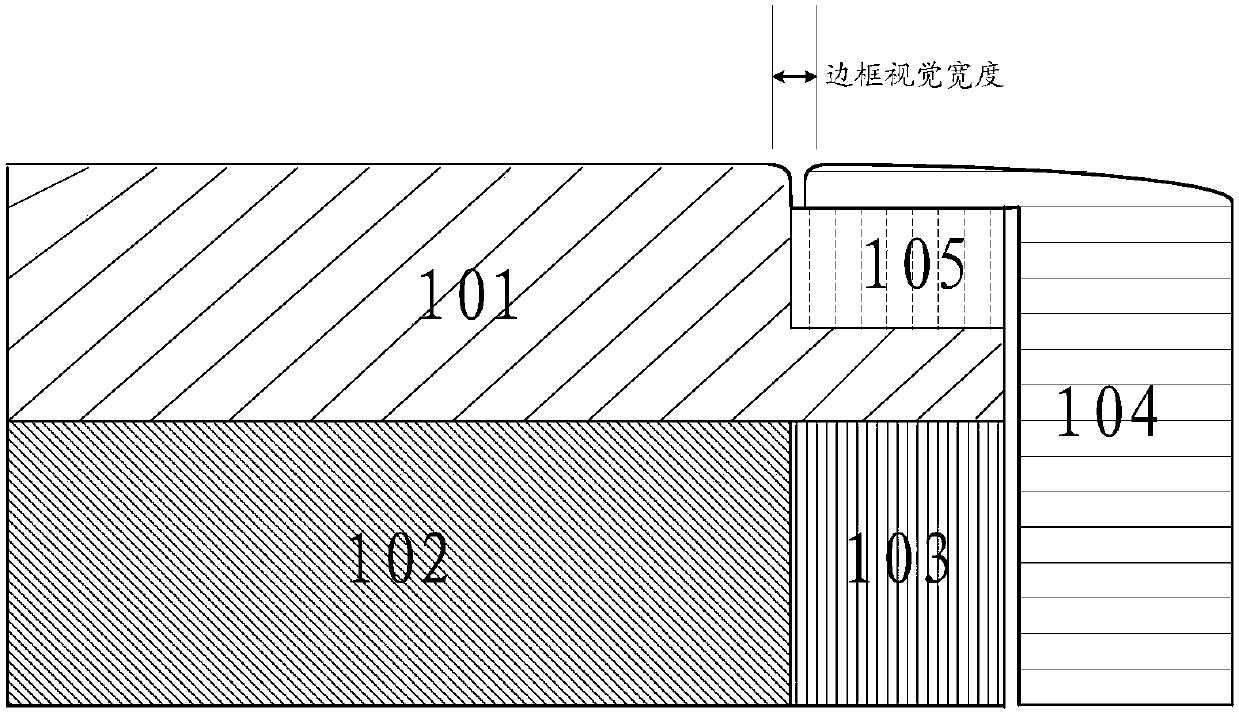
[0023] figure 2 A cross-sectional view of a display assembly provided for an embodiment of the present invention. Such as figure 2 As shown, the display assembly may include: a glass cover 101 , a display unit 102 , a light leakage barrier 103 and a housing 104 .

[0024] The glass cover plate 101 includes a first part and a second part, the upper surface of the display unit 102 is bonded to the lower surface of the first part, and the anti-leakage baffle 103 is arranged between the display unit 102 and the housing 104, and the upper surface of the anti-leakage baffle 103 is The surface conforms to the lower surface of the second part.

[0025] The size of the glass cover 101 is larger than the size of the display unit 102, but considering that the thickness of the anti-leakage b...


PUM


Abstract

The invention relates to display assembly, an installation method thereof and a terminal. The display assembly comprises a glass cover plate (101), a display unit (102), a light leak preventive baffleplate (103) and a casing (104). The glass cover plate (101) comprises a first part and a second part, the upper surface of the display unit (102) is fit to the lower surface of the first part, and the upper surface of the light leak preventive baffle plate (103) is fit to the lower surface of the second part; the glass cover plate (101) is of an integrated step structure, and the first part is thicker than the second part; and the casing (104) includes an extension frame extending towards the glass cover plate (101) in the top end, the upper surface of the extension frame and the upper surface of the first part are positioned in the same horizontal plane, and the lower surface of the extension frame is bonded to the upper surface of the second part. The upper surface of the glass cover play in the display assembly is processed into a step, so that the casing and the glass cover plate are equivalent in height, and a black edge problem in the terminal is solved.

Description

technical field [0001] The invention relates to the field of mobile communication equipment, in particular to a display component, a terminal and a method for installing the display component. Background technique [0002] The screen-to-body ratio of terminal display screens has become the selling point of current products, but the current terminal product structure design has problems such as light leakage, false touches, and increased chances of broken screens, and it is still unable to achieve true borderless. [0003] At present, TP-LCD is installed from top to bottom. The product shell supports TP-LCD steps hidden inside the product. The structure of TP-LCD is: the length and width of the glass cover are larger than that of the liquid crystal display (LCD) Size: The LCD size is larger than the display area, so there is a problem of displaying black borders, which causes the terminal to display black borders and non-display areas that are too large. As a result, the scre...

Claims


Application Information

Patent Timeline
Patent Type & Authority Applications(China)
IPC IPC(8): G02F1/1333
CPCG02F1/1333
Inventor 李延豪
Owner HUAWEI DEVICE CO LTD
Learn More